|
|
Post by Haines Garage on Dec 17, 2014 17:29:35 GMT -5
Work the rope seals into position with my fingers, try to keep an even amount of rope above its seat as pictured. 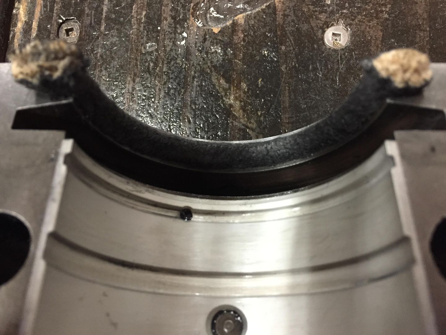 After seals are in by hand, I use my fashioned tool to seat them. I gently press, using a side to side rocking motion. 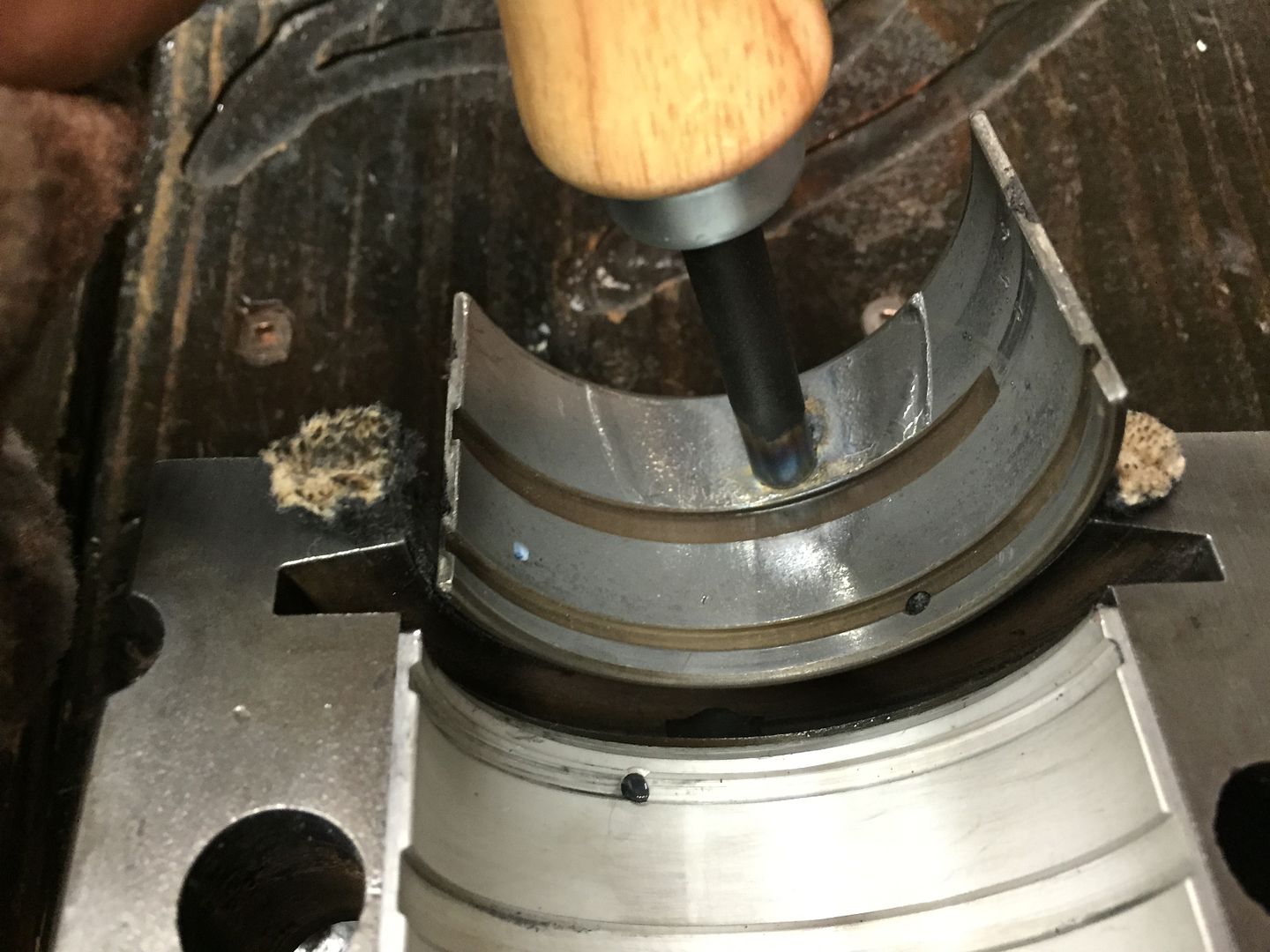 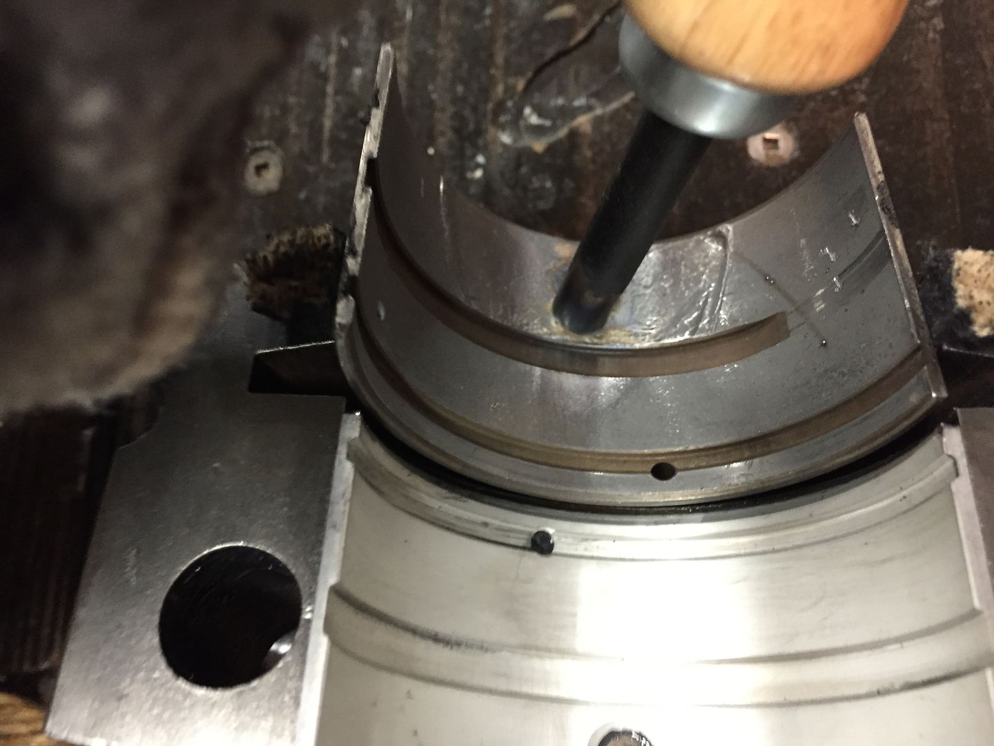 After set, I use the tool to hold the rope in place. I use a new utility blade to NOT CUT, BUT PLACE A SMALL TICK ON THE ROPE.  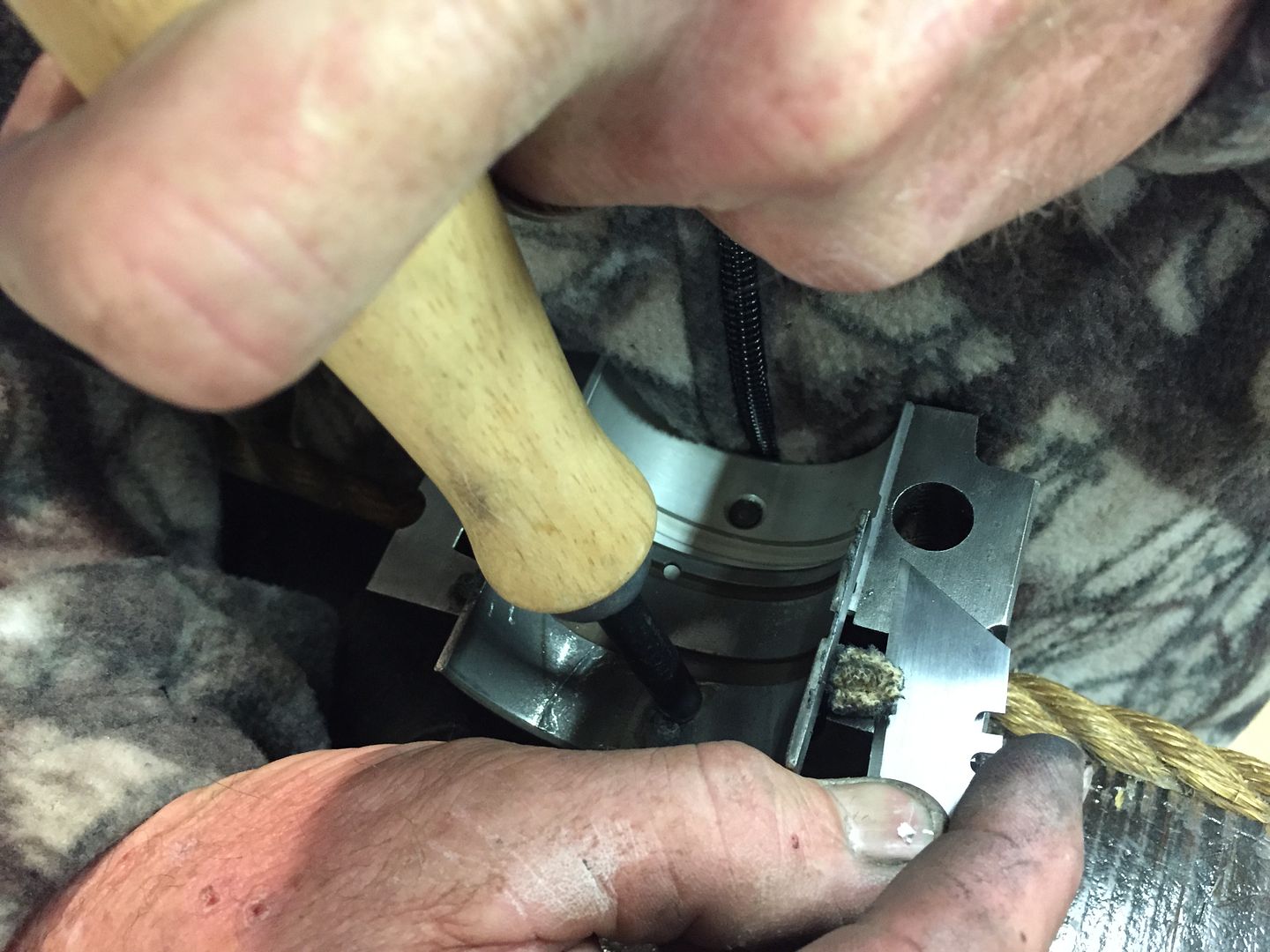 I then use extremely sharp scissors to cut the rope just above the tick I made with the razor. This leaves a very small amount of material above the cap and the block. 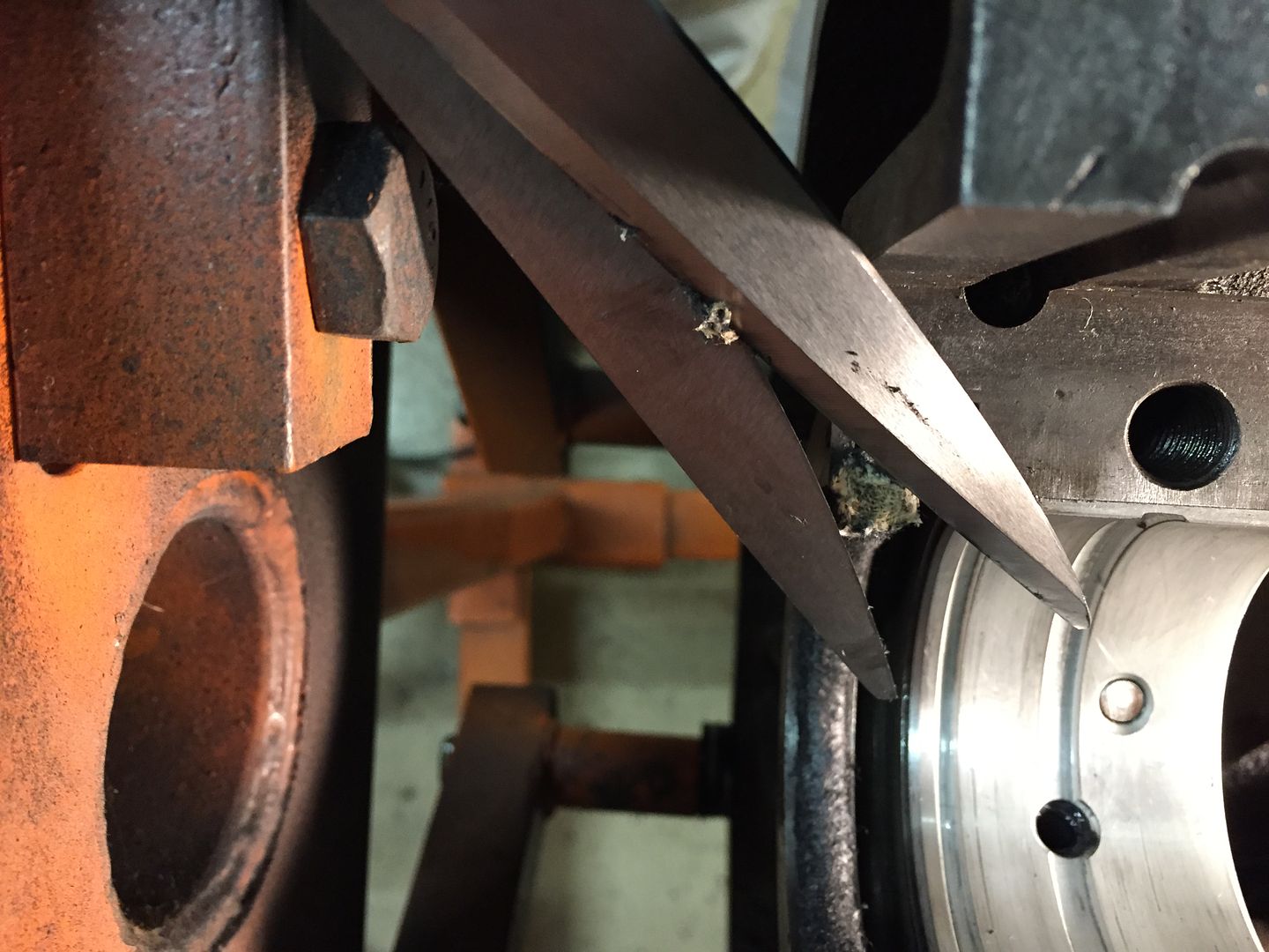 I then again, using the tool, do one last press. Finished seal looks like this 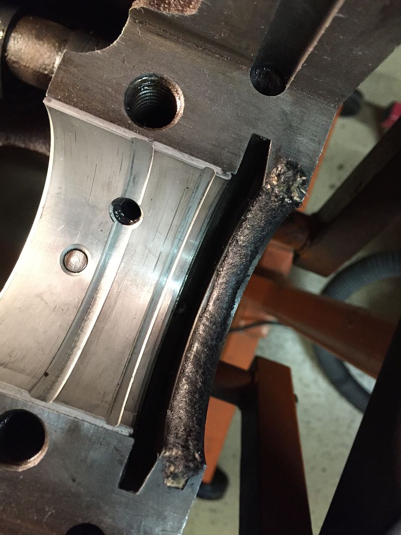 I am not going to be starting my engine immediately, so I place a dab of grease on top of the seals and smear it with my clean finger. 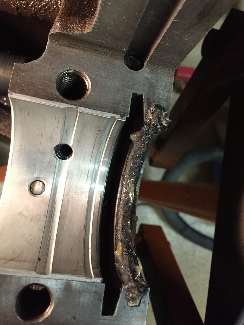 Rope seals are ready to be installed. |
|
|
|
Post by Haines Garage on Dec 17, 2014 21:58:28 GMT -5
Lube all Main bearings and journals on the crankshaft with a coat of assembly lube. Be careful not to get lube on the cap mating surfaces or bolt/thread areas. Excessive lube will give false torque readings. Gently lower the crankshaft into the block. Install the center and front cap. ( As in the thread previous Plastigauge Check) I then apply Black RTV sealant to both the block mating surface and the cap in the rear main seal area as pictured. I use an artist brush to be able to evenly apply, and KEEP THE RTV OFF THE ROPE SEAL. 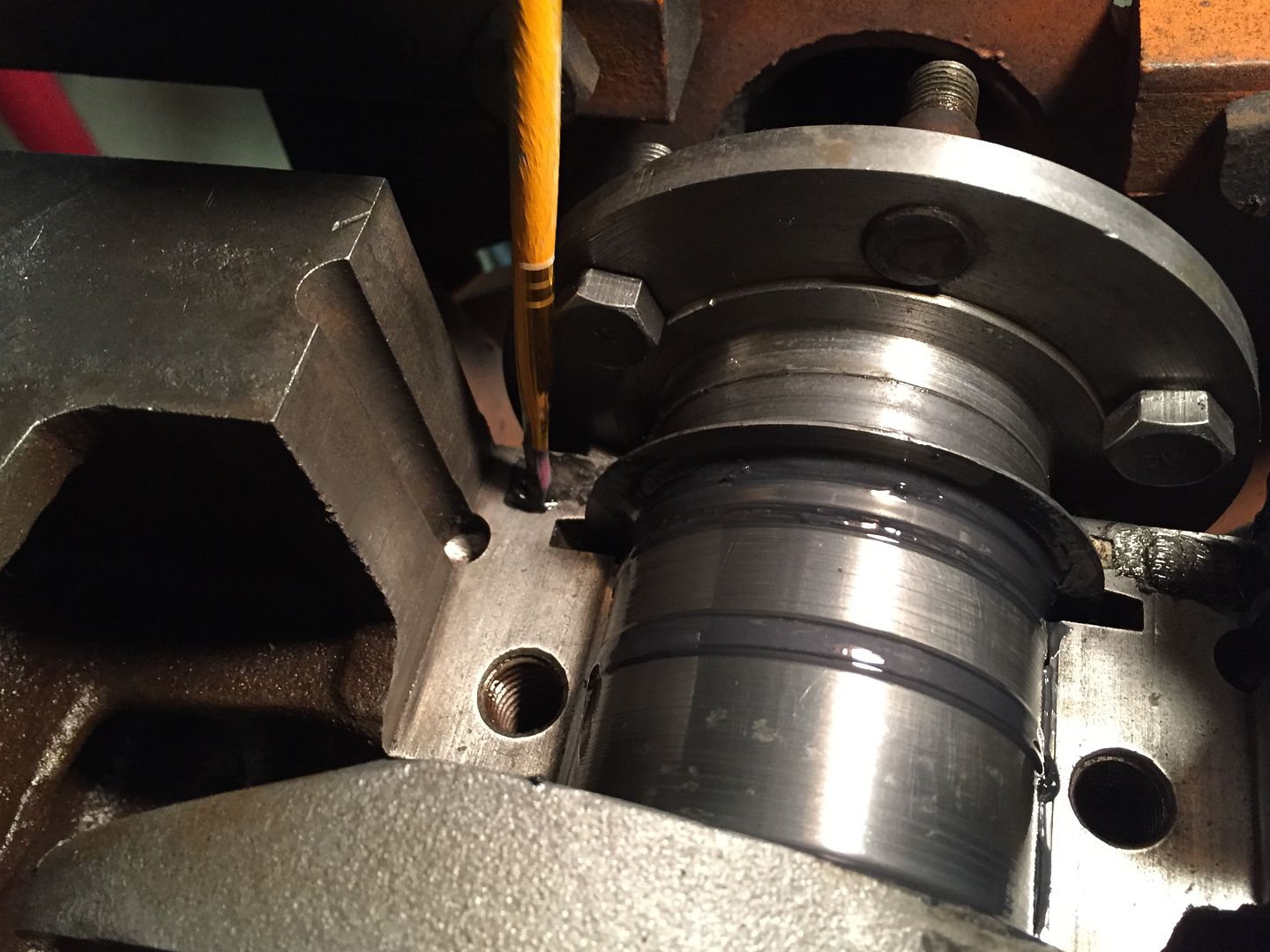 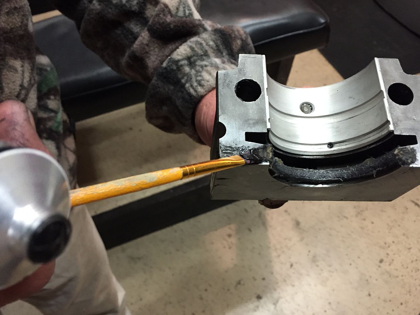 The RTV is applied to the entire "L" shape of the block and cap. Install rear cap. Notice the alignment marks on the cap and block. 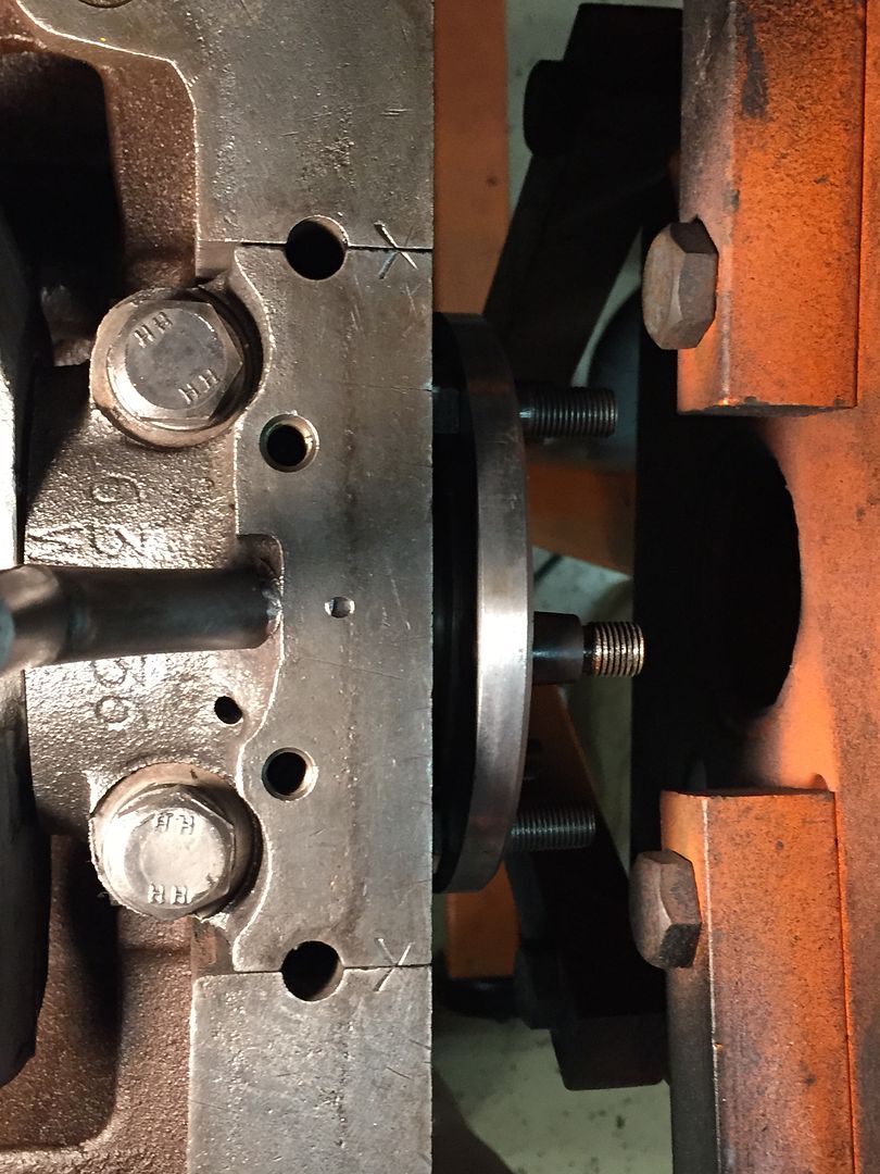 At this point, I tighten the center cap bolts first, then rear then front. After each cap is tightened, I spin the crankshaft a full revolution to insure that there is no binding. If you fell ANY STOP! Something is wrong. Locate problem before proceeding. Crank should turn freely by hand. Torque caps alternating back and forth on the bolts, I only turn 1/4 turn with the torque wrench at a time to insure cap closing straight and correctly. Torque all bolts to 50 Ft Pounds first, then to 65 Ft Pounds. 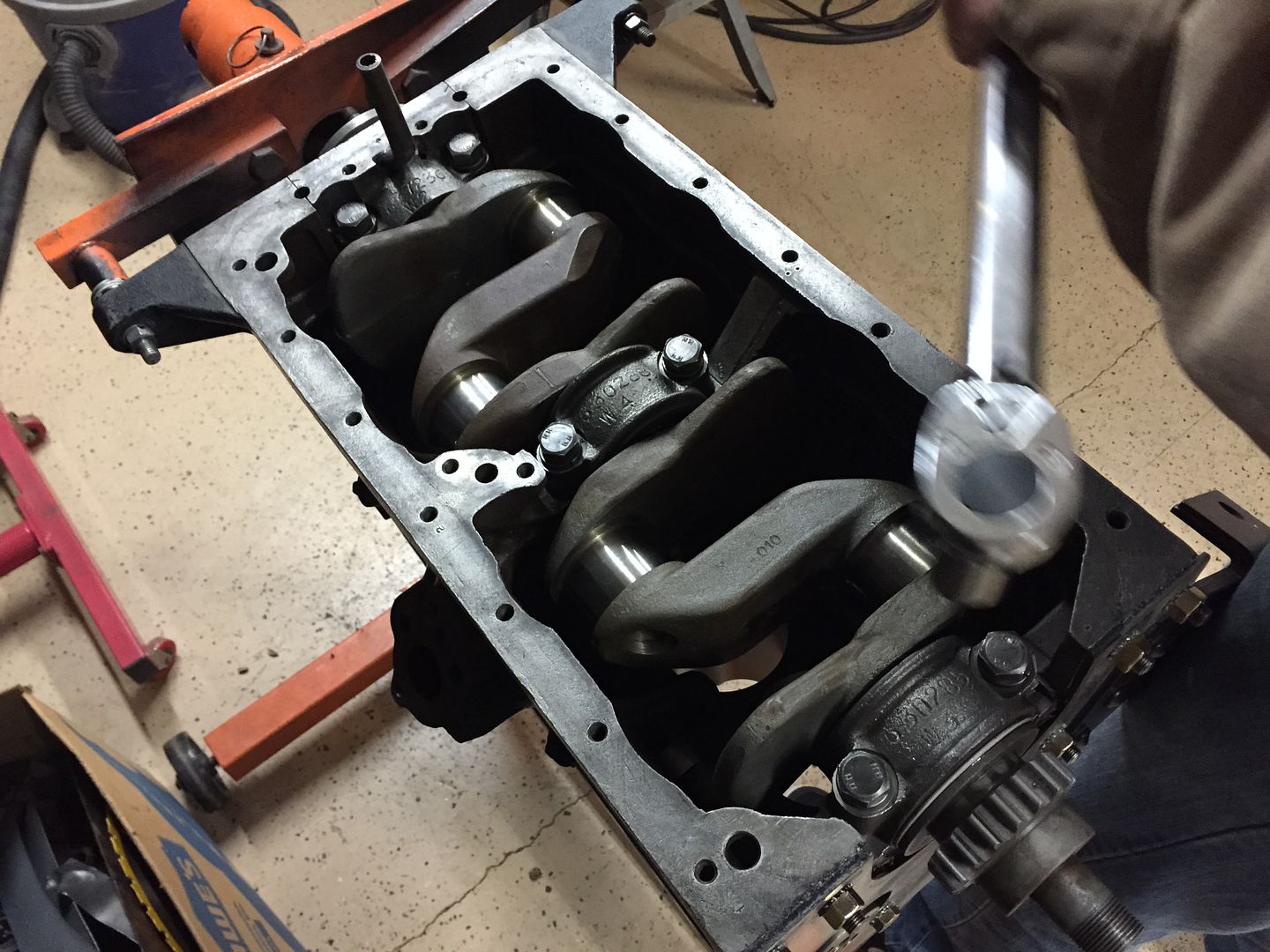 |
|
|
|
Post by Haines Garage on Dec 17, 2014 22:03:03 GMT -5
After I am sure the crankshaft spins freely, I need to check the end play. You can take your hands, and push the crank slightly back and forth. Shove the crank completely forward. Using a perfectly straight edge, I use a metal rule. Place the edge of the straight edge across the block as show. 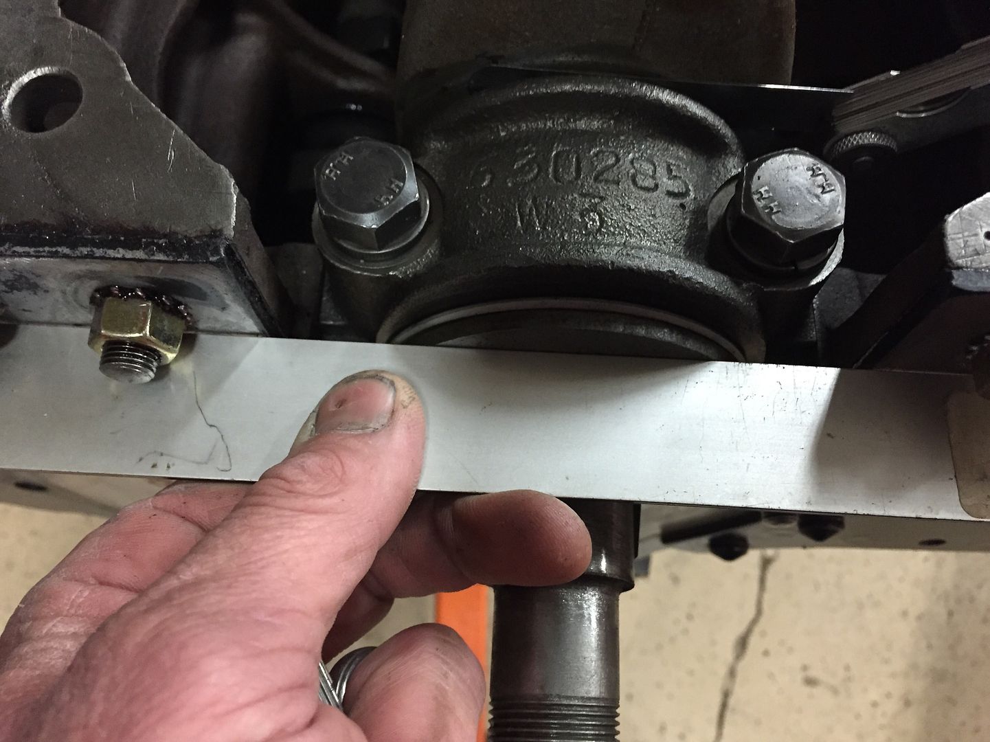 The space where the crank touches the rule, is them measured with a feeler gauge. I have not space, between. When I disassembled the engine, I found no shims. If there was a space measured, crankshaft shims will be required. Standard end-play as stated in the WO manual is .004 to .006. Shims are available in packages with each shim measuring .002 If your end-play measurement is more than .006, you will have to add shims to correct. |
|
|
|
Post by Haines Garage on Dec 21, 2014 18:29:12 GMT -5
Installing The Pistons And Ring Set I am using a set of Hastings cast iron rings.  Make sure that you first read the instruction sheet provided. Different manufacturers may have slight changes in the proper installation of their ring sets. 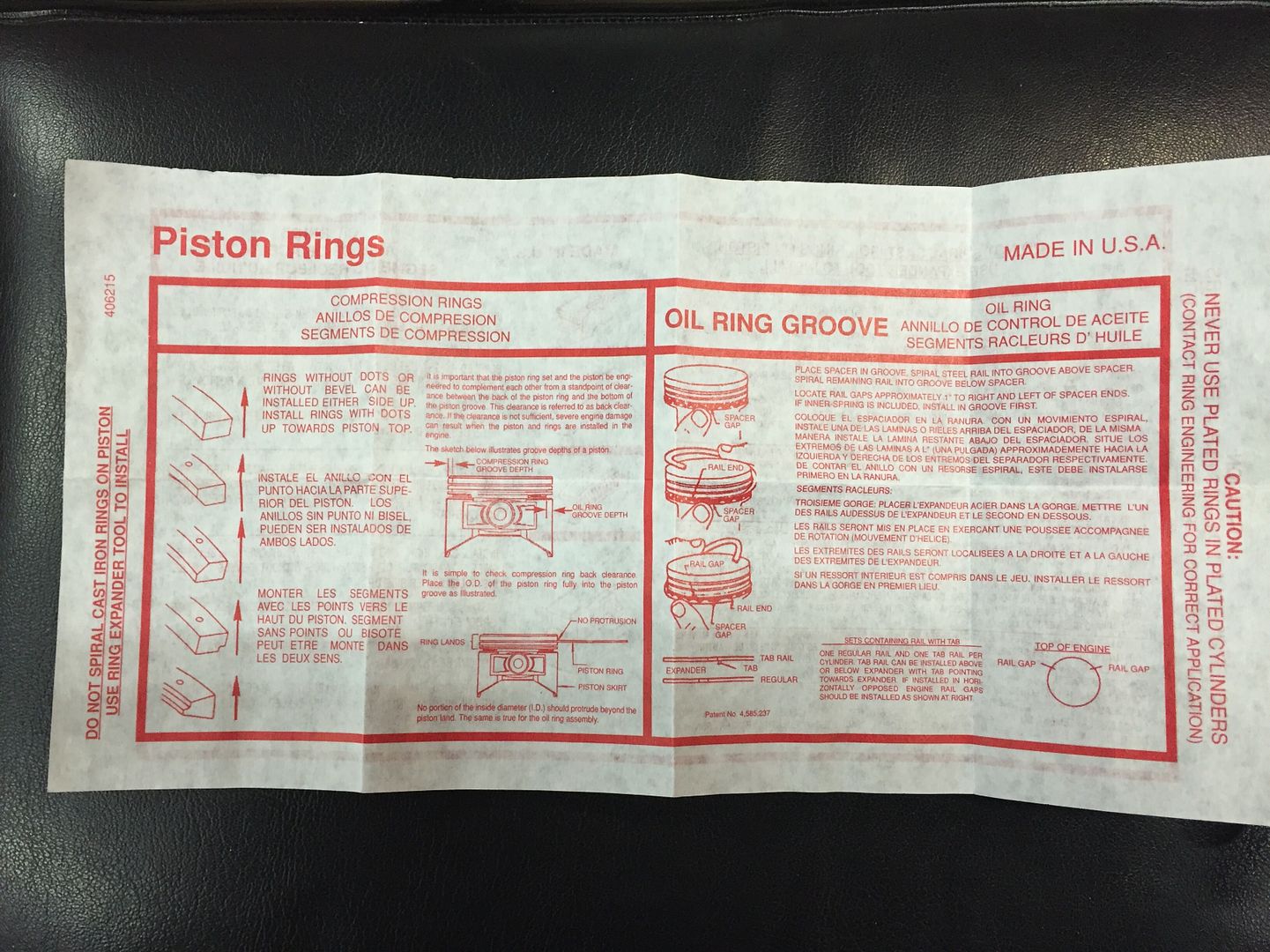 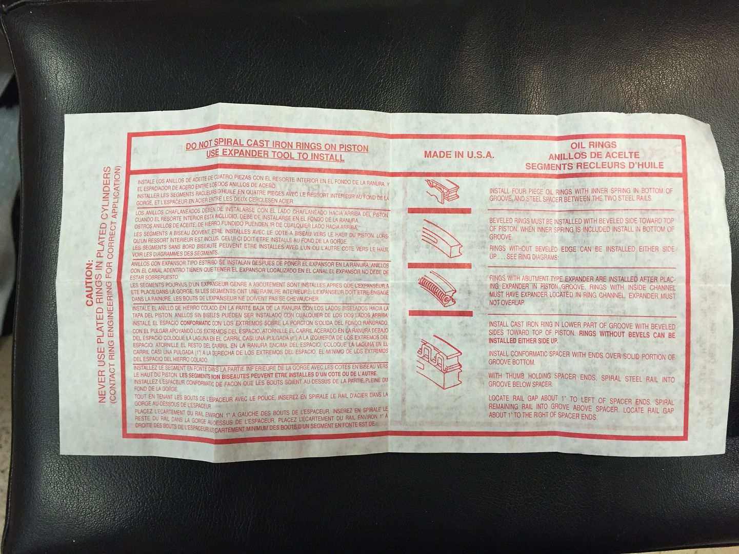 This is a nice feature on the folding tabs of the box. 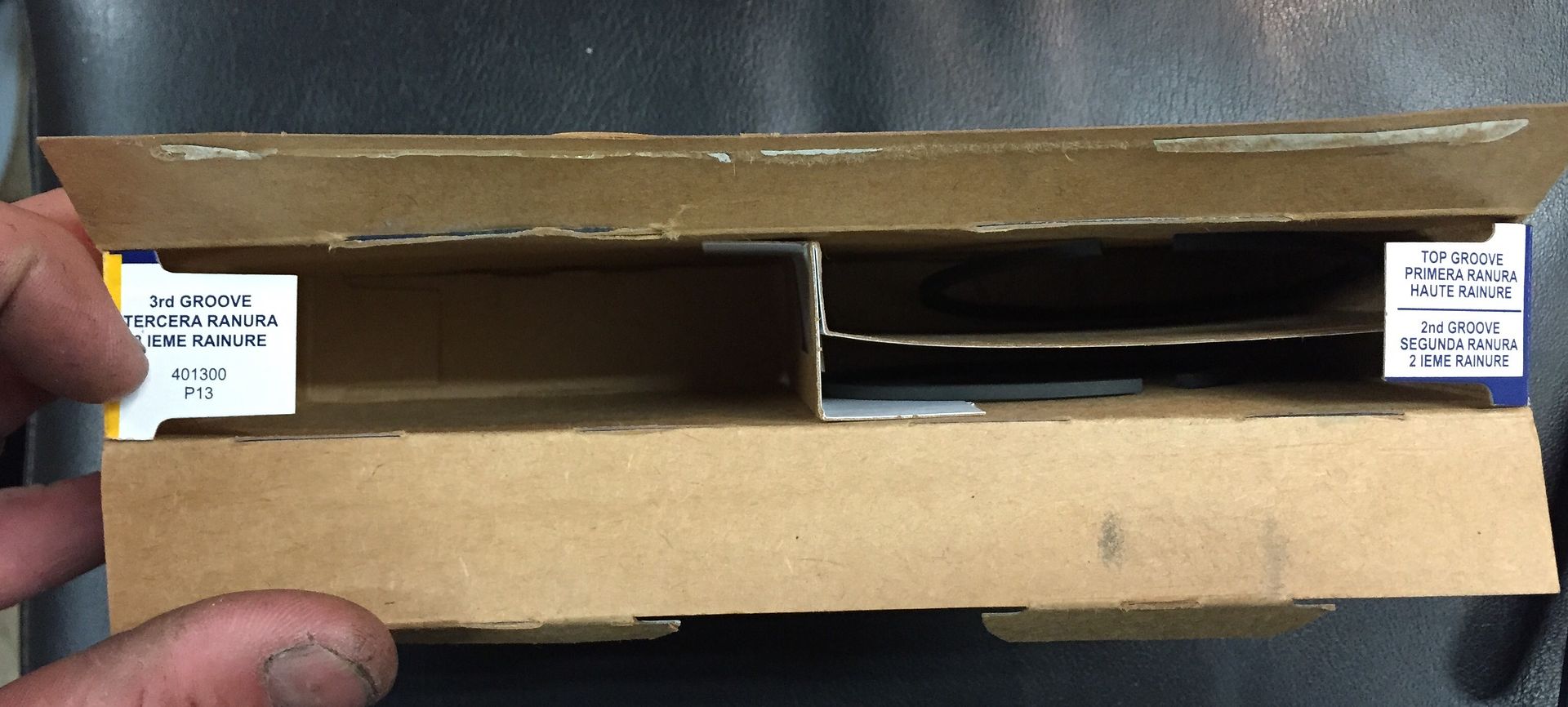 |
|
|
|
Post by Haines Garage on Dec 21, 2014 20:13:56 GMT -5
I am using new pistons and rings. The block has been bore .040 over standard.
When purchasing new pistons and rings, make sure you have the correct size for your engine.
Meaning your pistons and rings set will match your machining over standard.
Pistons and rings are available For the L134 Engine in Standard, .020, .040. .060, and I have seen even .080.
* It is not recommended on the L134 to go higher than .060 as cooling issues may present themselves after that.
Before installing my rings, I want to check the end gap.
The end gap is the open space in the rings that allows installation, or the split in the ring.
Make sure that there is a coating of oil on the cylinder wall, and apply a light coat of oil to the outside of the ring itself. I test two of each of the top and second ring. New quality rings should be perfect, I choose to test as a precaution.
Gently place the ring into the cylinder in a corkscrew fashion.
Make sure the ring is at a 90 degree, or flat inside the cylinder. I install just slightly under the top of the bore.
Using a feeler gauge, measure the gap.
Manual Spec is .007 to .017
I also randomly check a few rings into the grooves of the piston.
Simply insert the out side edge of the specified ring into the ring gap on the piston.
Use a feeler gauge to measure the space between the ring and the top of the piston groove.
Manual specs are as follows on ring gaps for an engine that has been bored .040 over.
Top Ring .002 to .004 in
2nd Ring .0015 to .0035
Oil Ring .001 to .0017
Feeler gauges should fit your measured space snug with the gap you are measuring. Not loose and Not Tight.
After checking a few, I am satisfied that my rings are within spec, and proceed to install them
|
|
|
|
Post by Haines Garage on Dec 21, 2014 21:34:26 GMT -5
Oil Ring And Spacer Rings 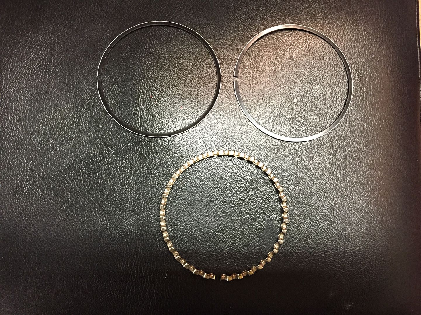 Install the Oil Ring on the lowest ring groove on the piston. Install the Bottom Spacer. Install The Top Spacer. This is done in a spiral fashion for all as pictured. 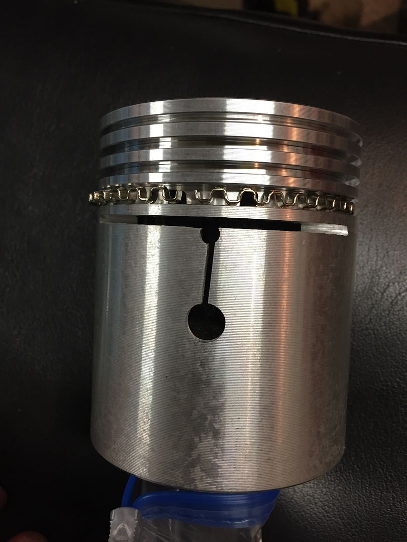 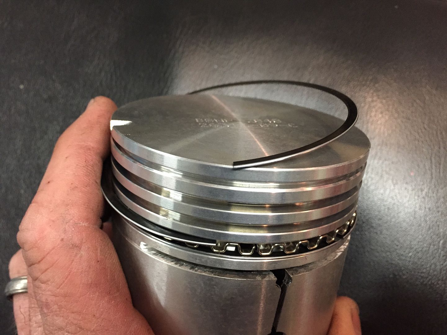 The top and second ring will be installed with this tool. As inexpensive as it is, I paid $6.00 for this one, it is most IMPORTANT! 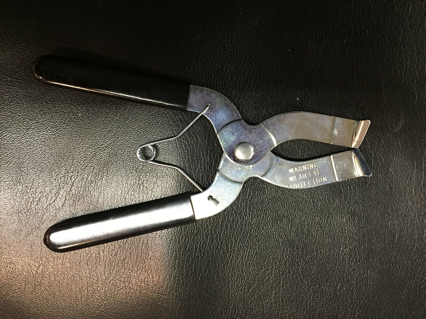 |
|
|
|
Post by Haines Garage on Dec 21, 2014 21:43:19 GMT -5
The piston ring expansion tool works very simply. You insert it into the gap in the ring, squeeze and expand. You don't want to expand the ring more than it takes to install it on the piston. 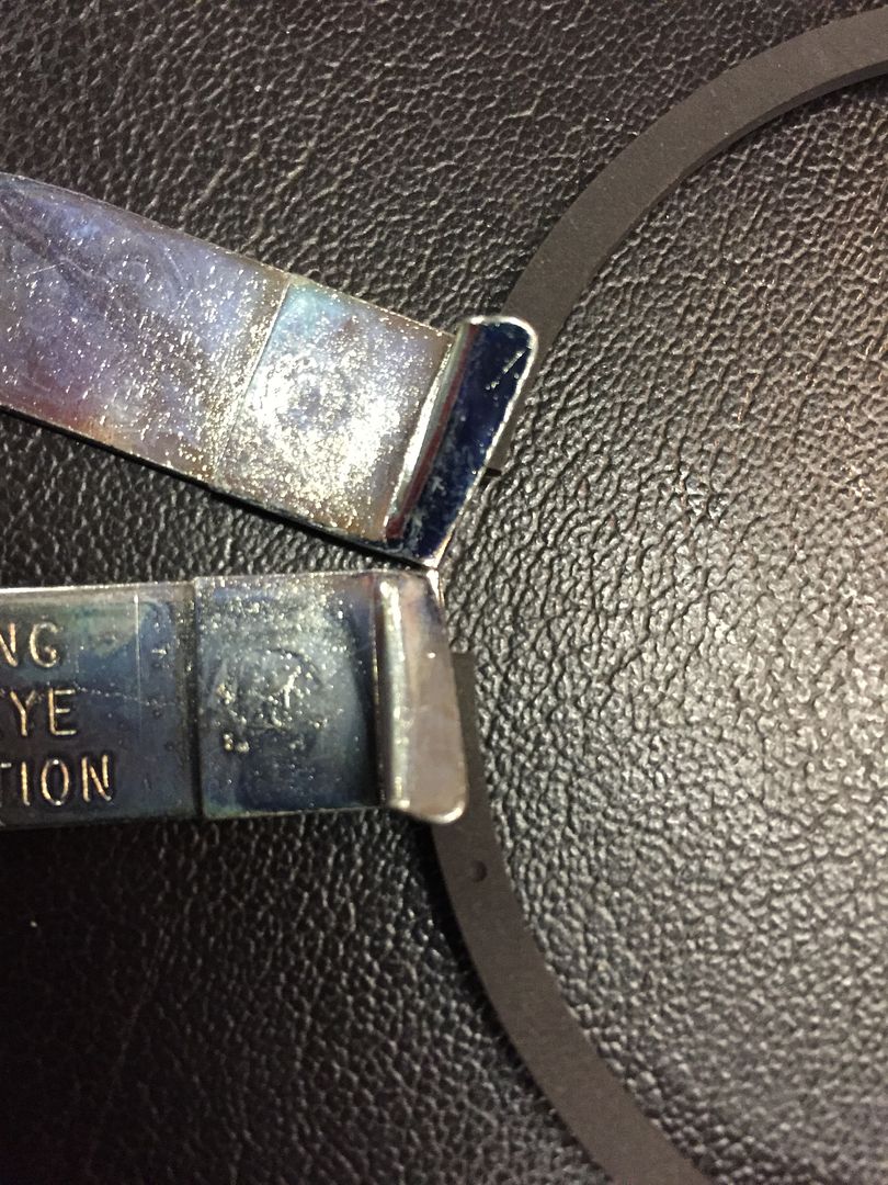 In this photo you will notice a DOT on the ring. In my ring kit, and commonly, The dot will indicate to install facing the top of the piston. 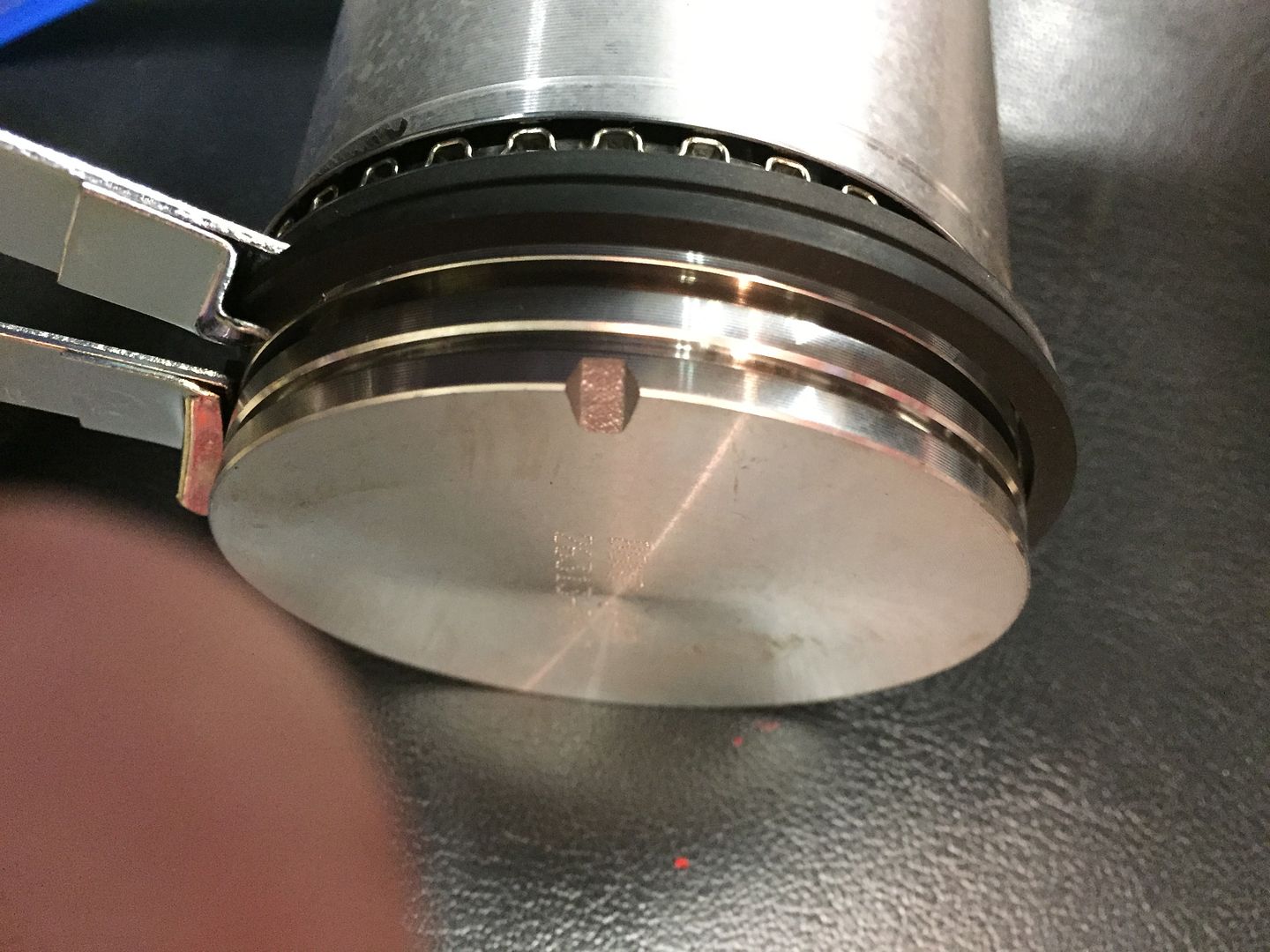 Expand the ring, and slip it over the Piston as pictured. I have gone past the correct groove to show how the installation tool works. Align the ring with the correct groove and release it. Rings will be loose, but stay in their correct location at this point. |
|
|
|
Post by Haines Garage on Dec 21, 2014 22:13:02 GMT -5
At this point with installing the rings, I am not concerned with their proper gap placement. The rings will move by finger, to their correct location before installed. Next I install the Connecting Rod Bearings. Here is a photo of the new bearings. Note the markings. They are for a .020 Under standard size. This means my Crankshaft has been ground .020 from standard size. 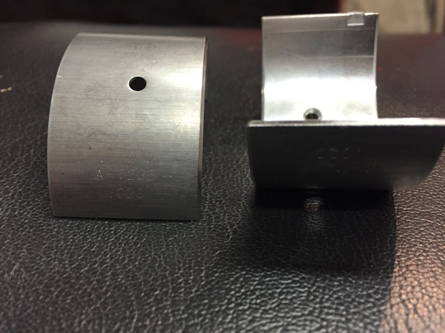 The "Resizing" of my Connecting Rods is fantastic. 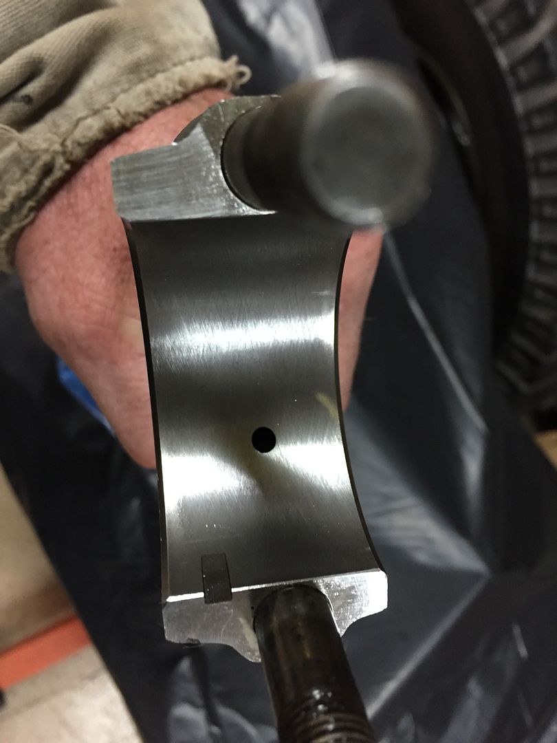 Clean nice and true round. Notice the oil hole. Bearings are inserted using the tab. It is pictured here. Bearings are installed according to their tabs. Make sure the oil hole lines up. I thumb press them in from both sides. You will feel a "click" so to say. Make sure the mating faces are clean, to ensure proper fit. 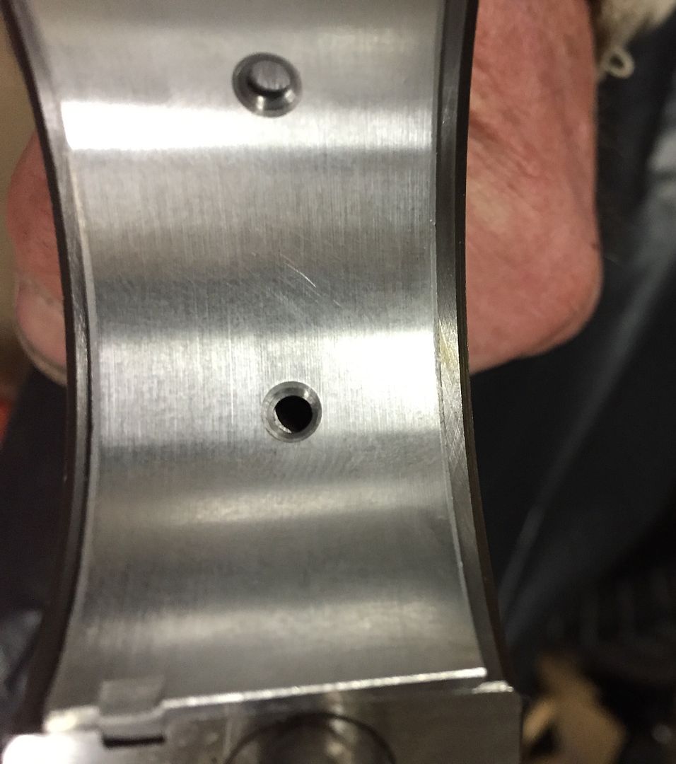 |
|
|
|
Post by Haines Garage on Dec 21, 2014 22:34:58 GMT -5
Install the bearing on the Connecting Rod Cap. 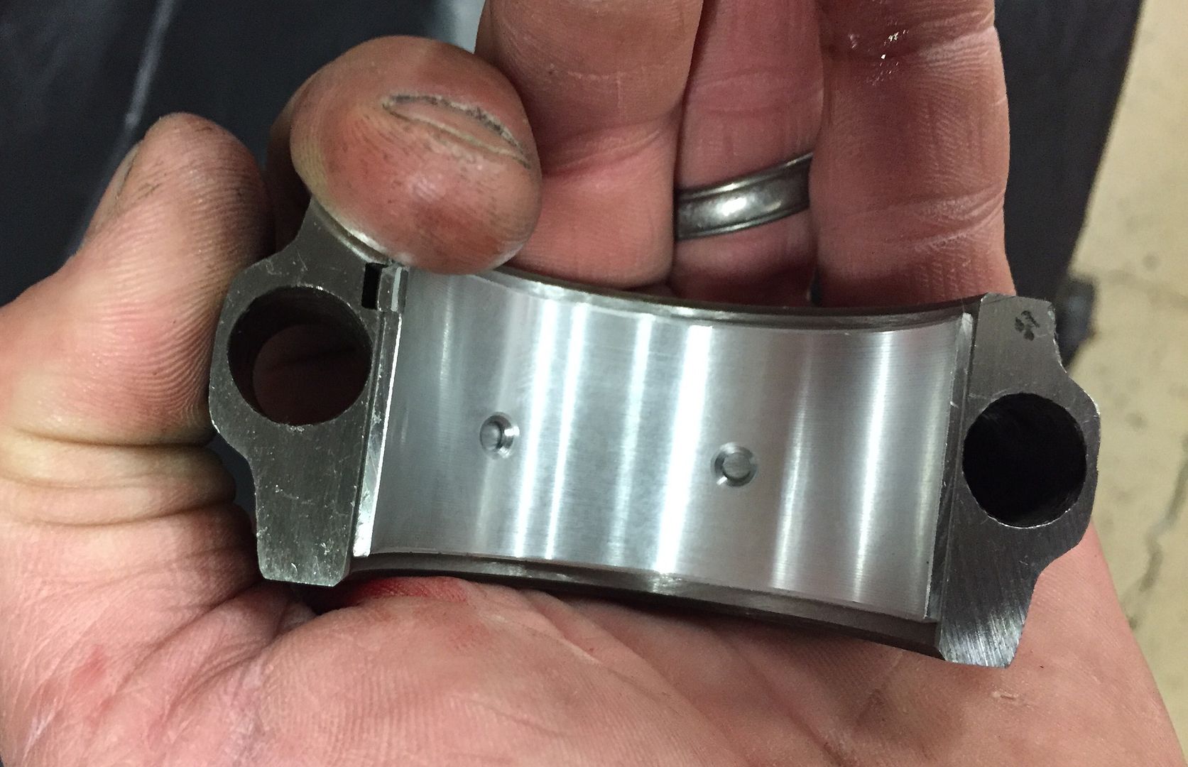 Again, the tab notates its correct installation. I repeat the same installation for each cap. Pistons are ready for final ring gap adjustment and installation. |
|
|
|
Post by Haines Garage on Dec 22, 2014 9:43:22 GMT -5
Check for cleanliness of the cylinder bores one last time. I wipe them out with a clean lint free cloth, then apply a coat of motor oil. Install two pieces of 3/8 fuel line, or in this case air hose to the threaded bolts on the piston. These will both protect from scratching the cylinder wall and crankshaft journal, they will also help guide the connecting rod onto the crankshaft journal. 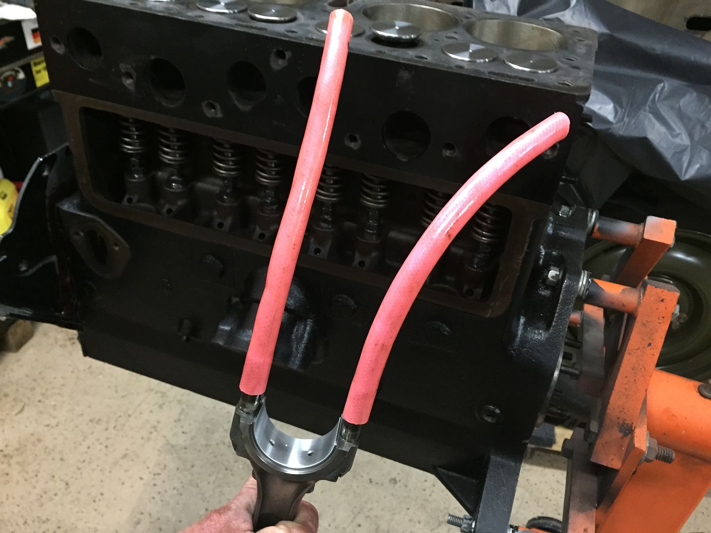 Now it is time to correctly space the rings. I simply turn them with my finger tip. Stating with the oil ring, I center it approximately 30 deg off the center of the oil t in the piston. The spacers according to the directions are placed with the gap 1 inch to either side of the gap in the oil ring. The second ring gap is set 40- 45 deg, from the oil ring gap to the right side of the piston . The top ring is placed 180 degrees on the opposite side of the piston. The idea being , most wear is on the outside of the piston (sides of the block). Ring gaps should be off set from the outside. 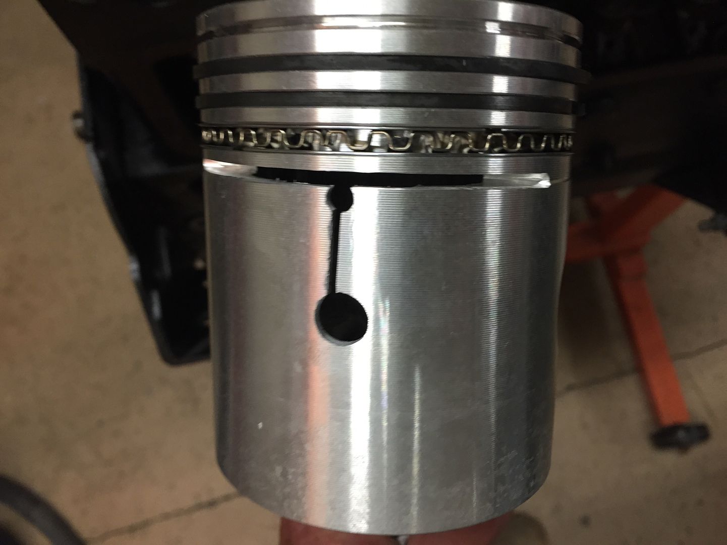 Coat the piston and rings thoroughly with motor oil. 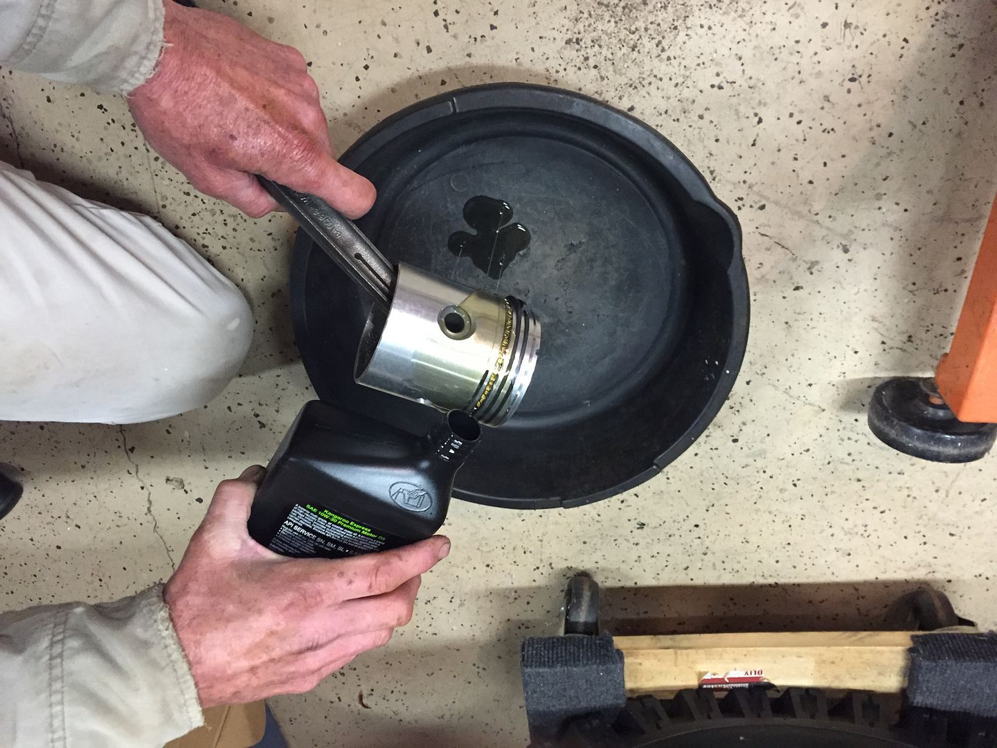 |
|
|
|
Post by Haines Garage on Dec 22, 2014 9:58:27 GMT -5
Using a ring compressor compress the rings. The sleeve of the ring compressor is only installed to cover the ring portion of the piston. The remaining portion of the compressor will guide the piston into the cylinder bore. Apply assembly lube to the journal of the crankshaft and the bearings on the connecting rod. 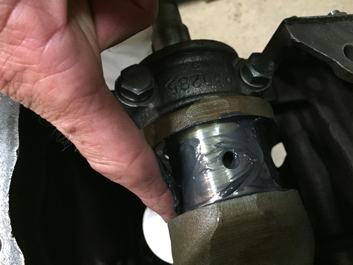 Lube the oil hole on the crankshaft journal with engine oil. 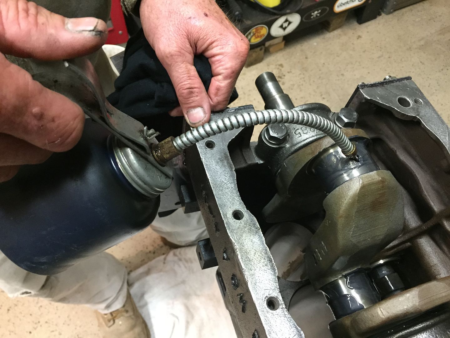 Make sure one last time that you are installing the correct piston in the correct bore location. The notch in the top of the piston faces the front of the engine. Rotate the crankshaft so the journal is at its lowest point in the block, or the oil pan side. Use two hands to guide the piston into the bore. The ring compressor will stop flat to the top of the block. Use the rubber hoses to guide the connecting rod onto the crankshaft journal. Use a wooded hammer handle to TAP the piston into place. 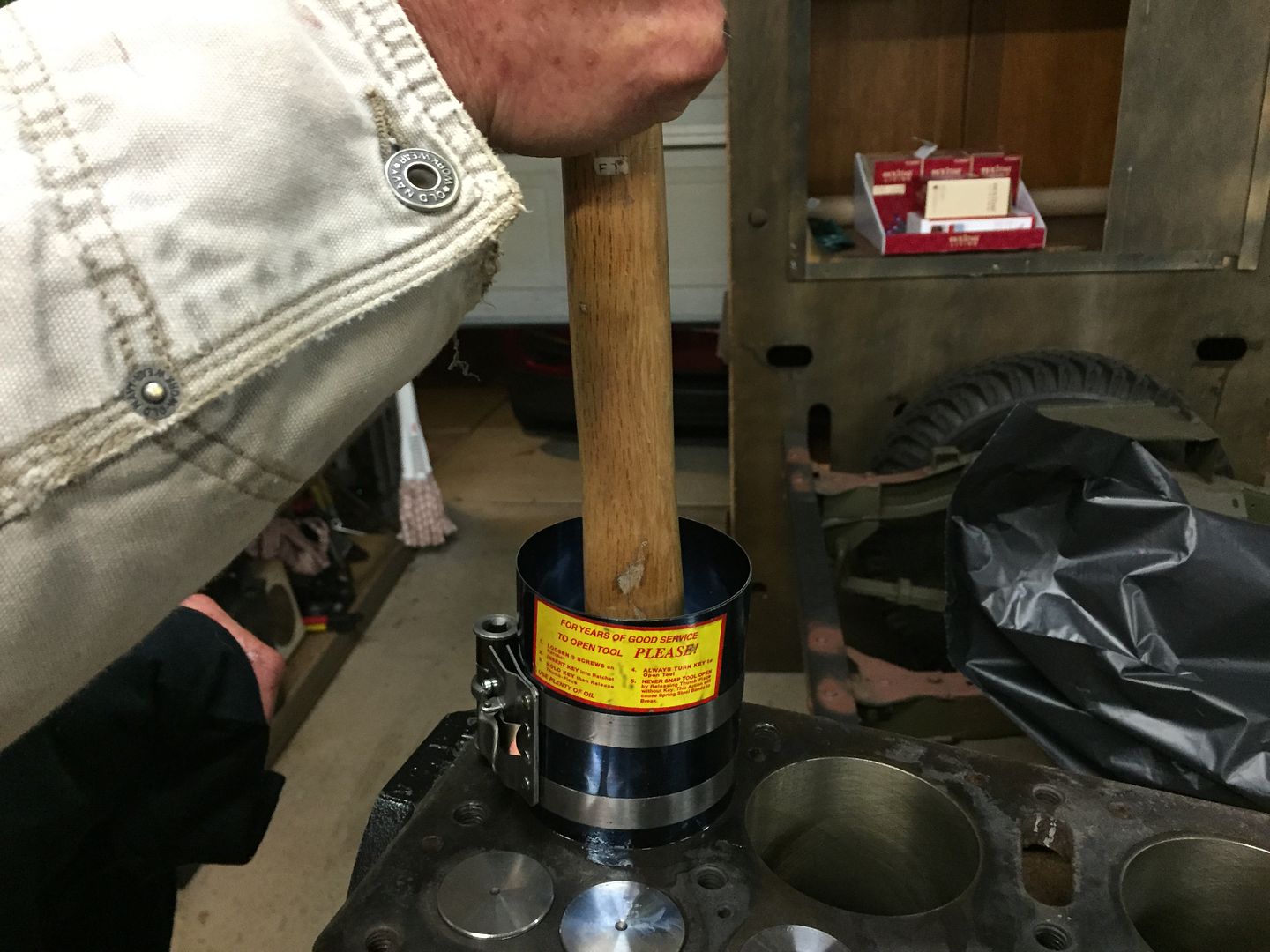 |
|
|
|
Post by Haines Garage on Dec 27, 2014 22:50:57 GMT -5
Repeat the same process for the next Pistons. I turn the crank a full turn before positioning the journal in its lowest position for the next installed piston. This insures that you have no binding. As you install more pistons, resistance on the turn will become greater. You are feeling for a bind. If this happens stop! You have a problem. Incorrect connecting rod placement could cause this. Here is a picture of the #2 and 3# Stamped Pistons. Note the thickness of the side of were it connects to the crankshaft. 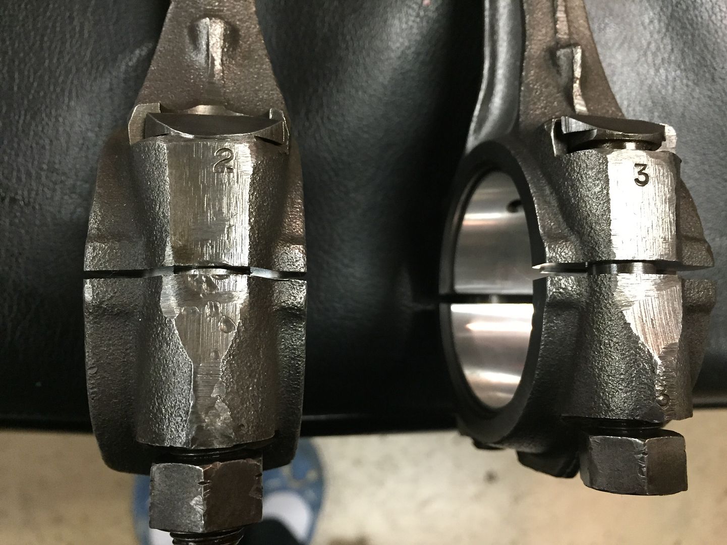 Here is a pic installed 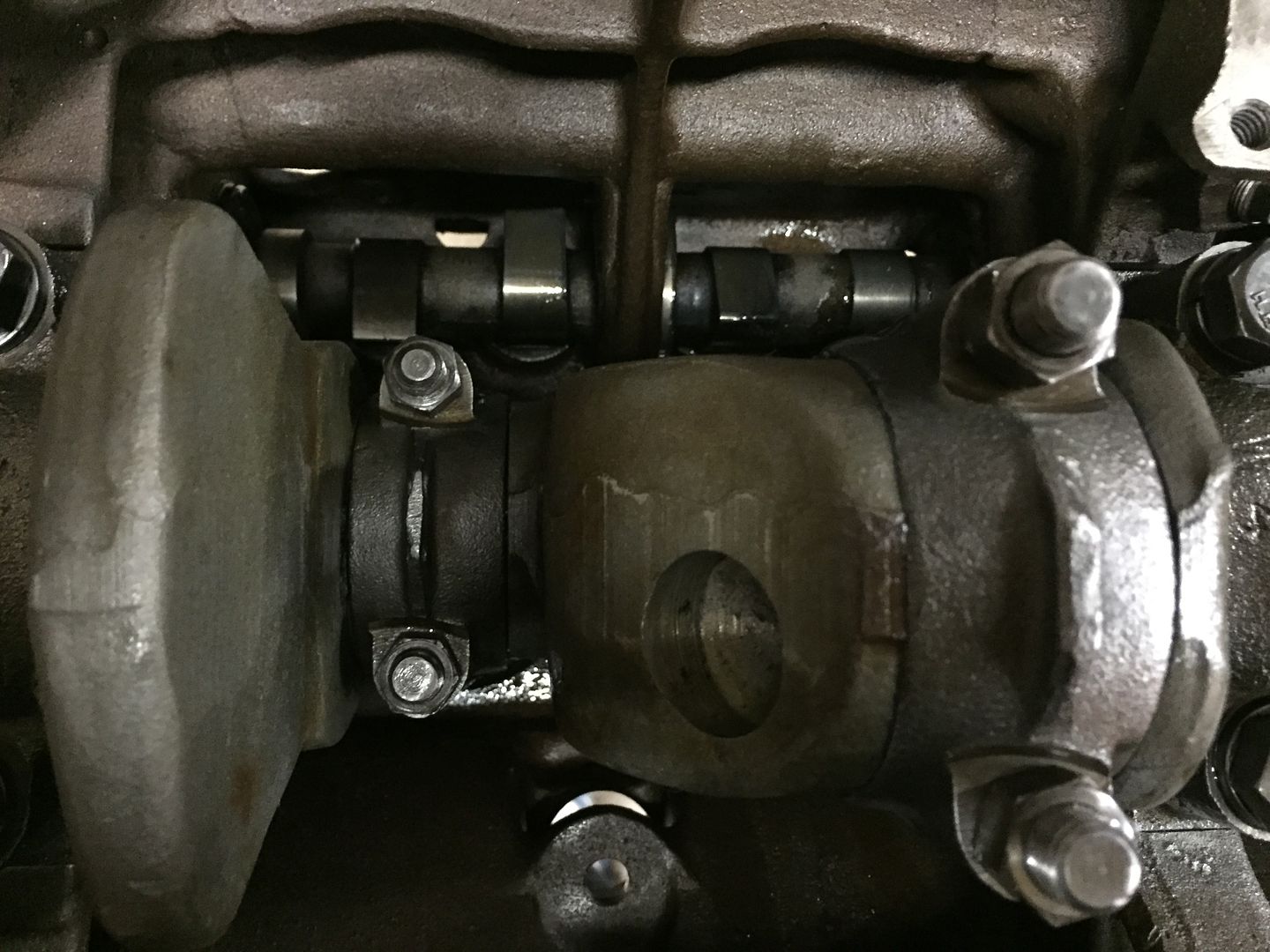 Install lock nuts to the piston bolts. The manual states to put them finger tight, and tighten 1/3 turn. DO NOT OVER TIGHTEN! 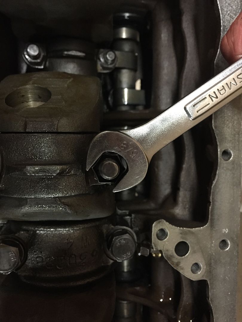 All lock nuts installed 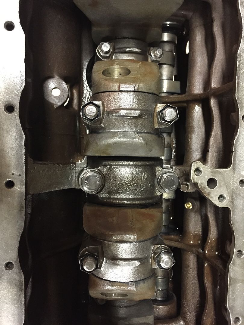 |
|
|
|
Post by Haines Garage on Dec 27, 2014 23:01:14 GMT -5
When all pistons are installed, I flip the engine over and check the connecting rod side play. Manual specs are .004-.010. Mine all check out at exactly .008 . I am safe to proceed. 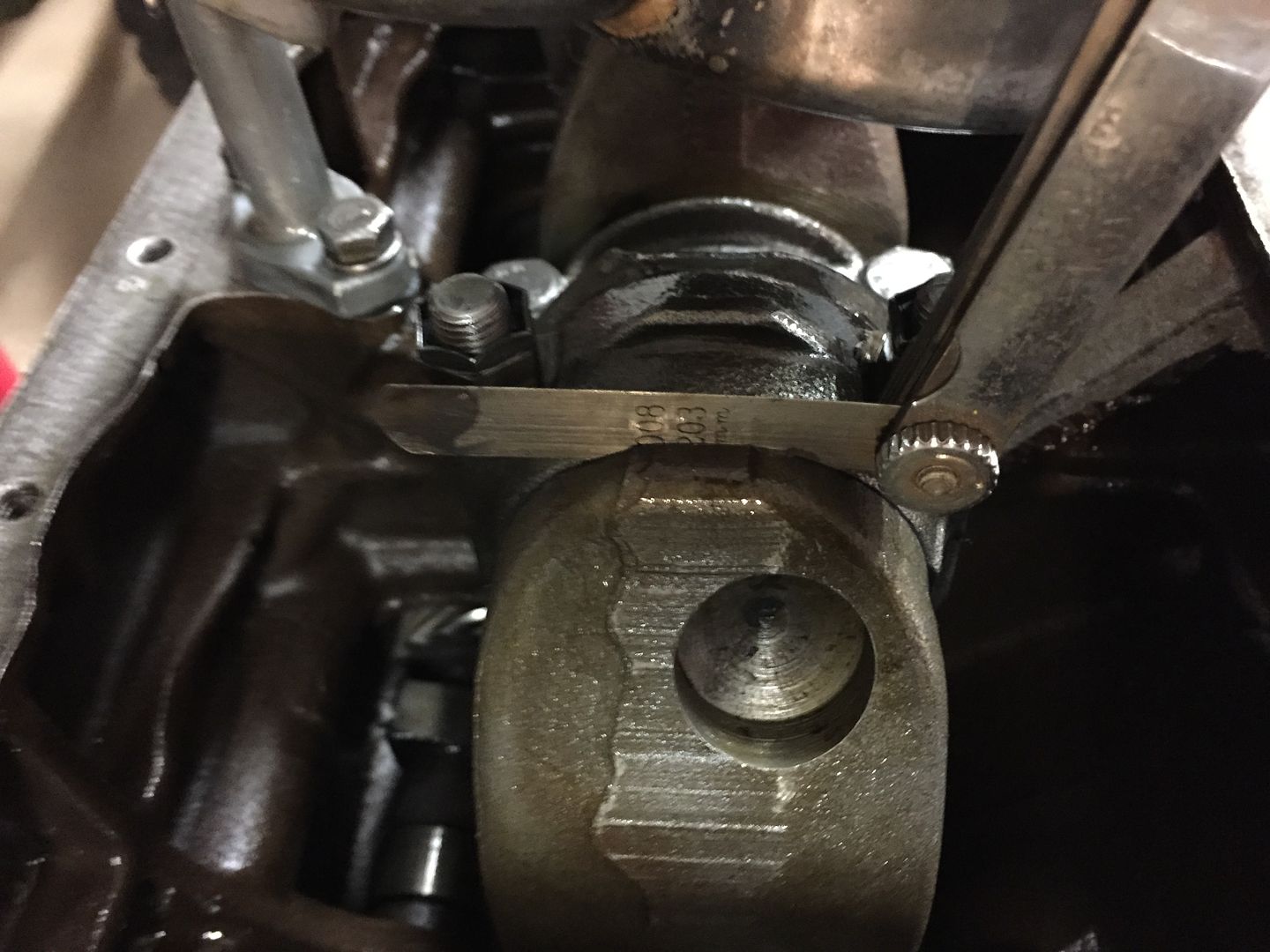 |
|
|
|
Post by Haines Garage on Dec 28, 2014 0:09:54 GMT -5
While the engine is in its upside down state, I install the oil float pick up. Before I install, there is a little work to be done. If you have ever disassembled an L134 oil pick up, they are notorious for holding debris. I have had many that I took apart, checked the screens, and found holes, tears, and clogs. EVEN AFTER SOAKING IN SOLVENT FOR MONTHS! I was fortunate to acquire a NOS sealed pickup. Just the head. 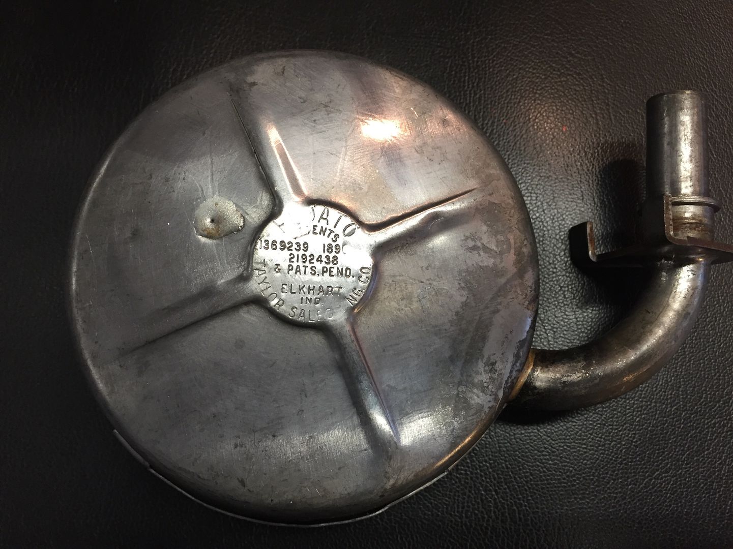 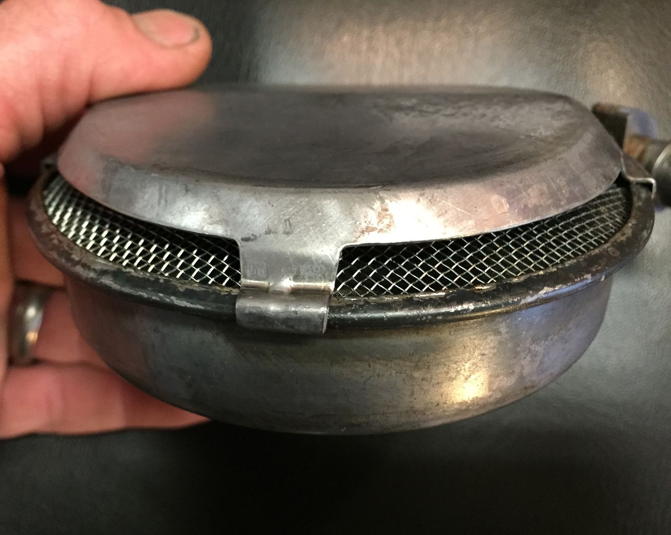 |
|
|
|
Post by Haines Garage on Dec 29, 2014 20:11:39 GMT -5
The Float I purchased did not include the mounting tube. I cleaned up the original, paying close attention to any debris left inside the tube itself, 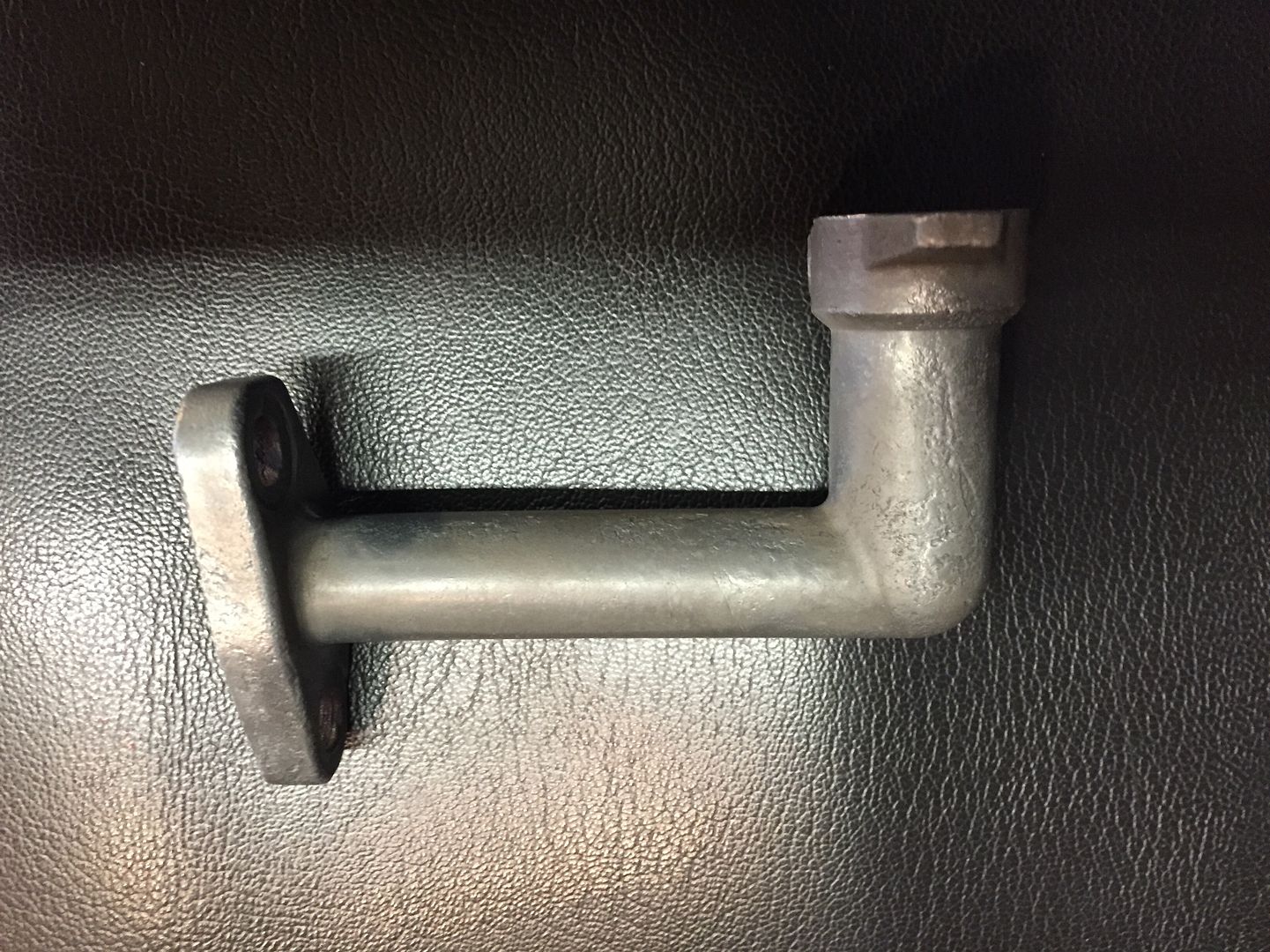 There is an O ring inside. I pulled and replace it with a match from the plumbing section at the local hardware store. 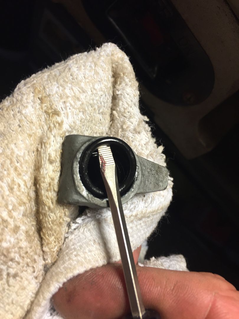 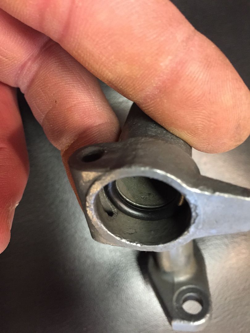 The tongue on the tube fits between the teeth of the oil float. I applied a small film of assembly lube to the float before I joined the two together. 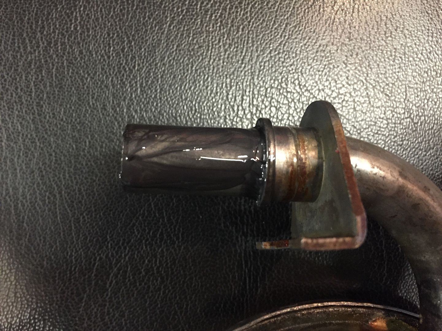 Insert a cotter pin in the hole as shown to keep the two pieces of the Float pick up together. Bend the key so that it will not interfere with it moving up and down. 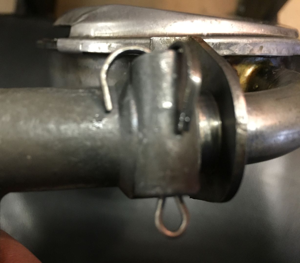 |
|
|
|
Post by Haines Garage on Dec 29, 2014 22:12:32 GMT -5
Before Installing the Oil Float to the block, test fit the float and check that mating surfaces are flush. Then clean the mating surfaces with lacquer thinner. I install the gasket dry. 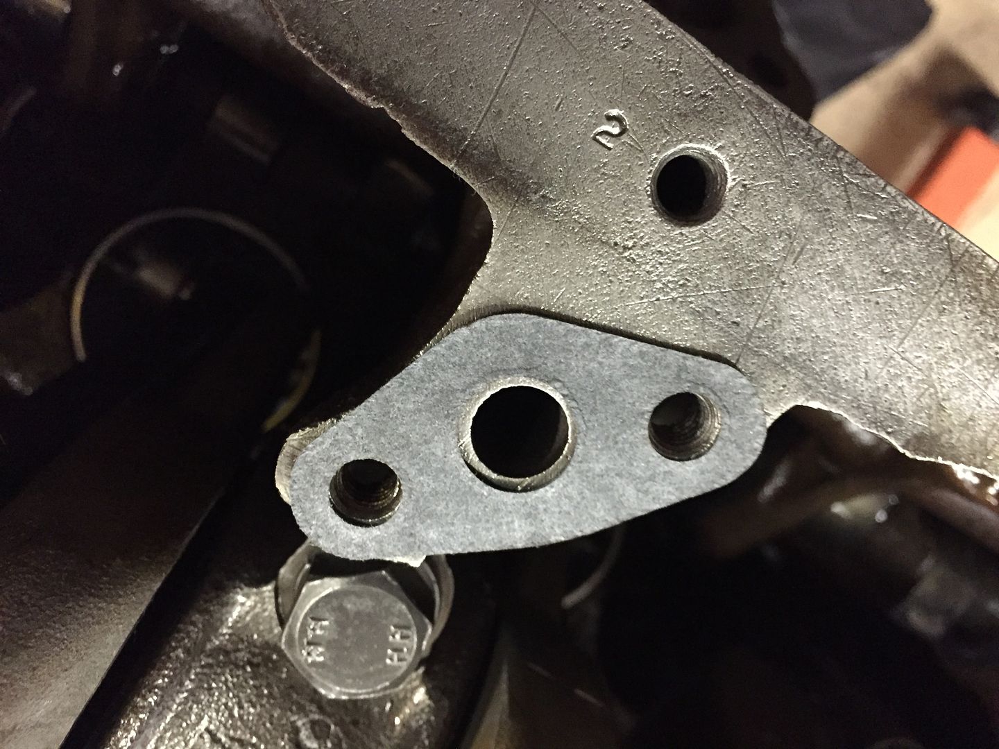 Then I apply Loctite red to the bolt threads, install lock washers and bolts. Finger tight, then torque to 18 ft pounds. 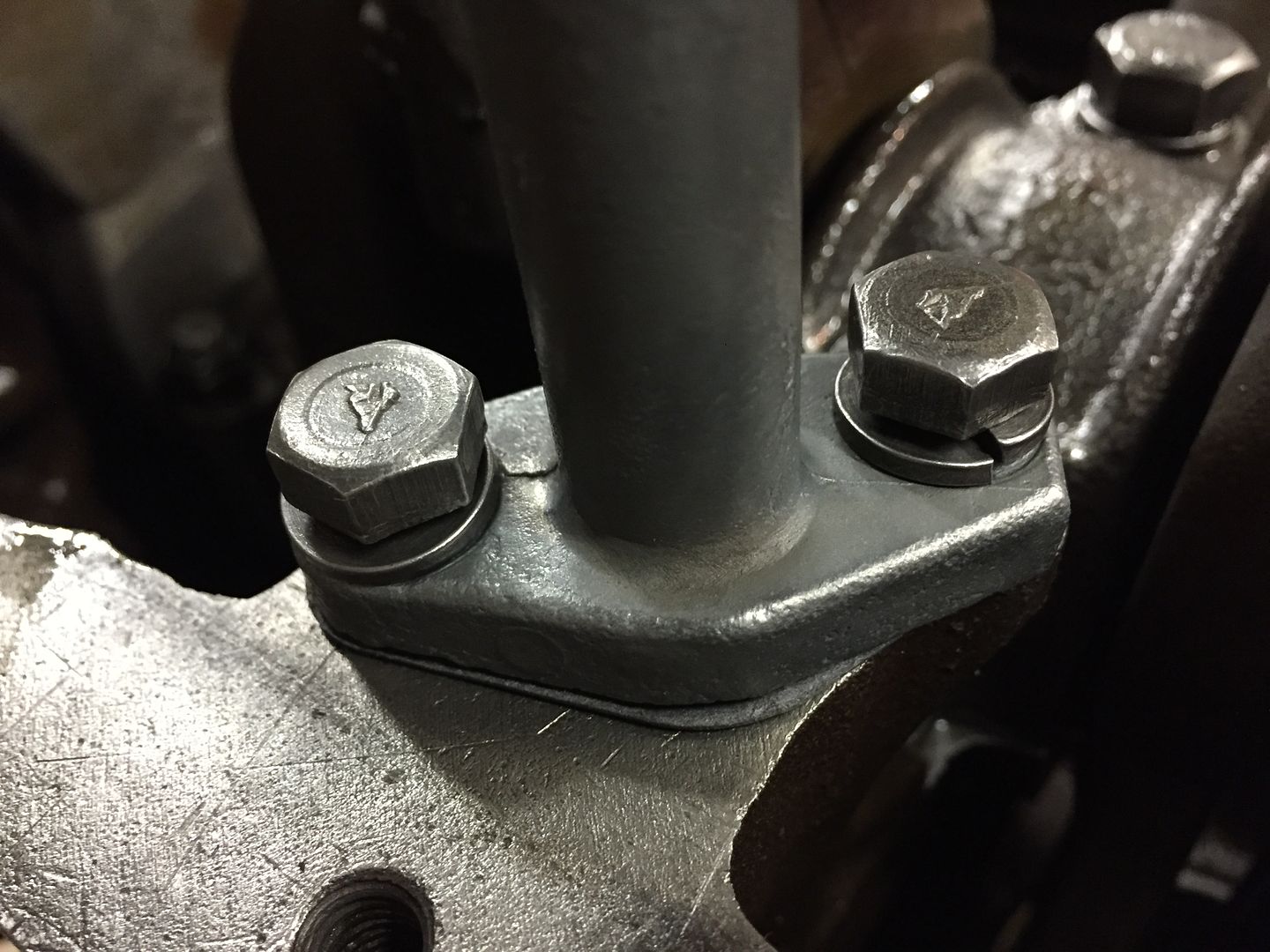 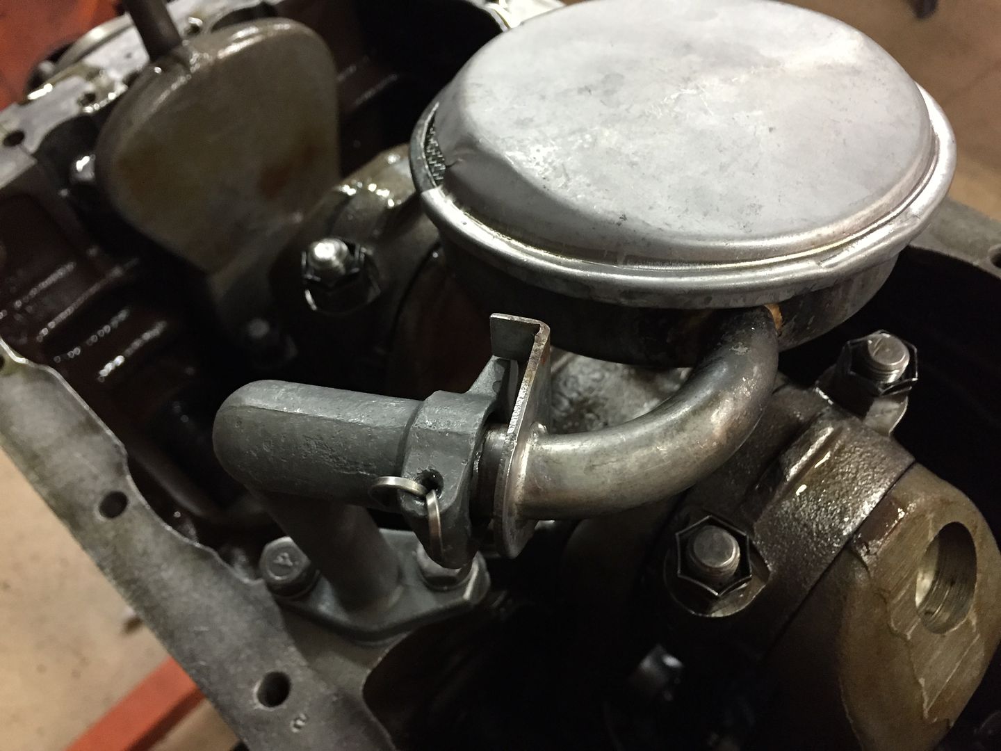 Make sure that the float in its lowest position will not touch the crank shaft. I do this by simply spinning the crank a rotation. |
|
|
|
Post by Haines Garage on Dec 29, 2014 22:24:40 GMT -5
Tim Hawkridge made a great point in the comments thread for this build. He mentioned that many time the area of the Oil Float Pickup can be distorted by over tightening. This area of the L134 is important. Any air leak at this connection point will cause poor priming and effect oil pressure. I thought I would add a way to check and correct if necessary. Place the float tube in a vice. Check with a straight edge. 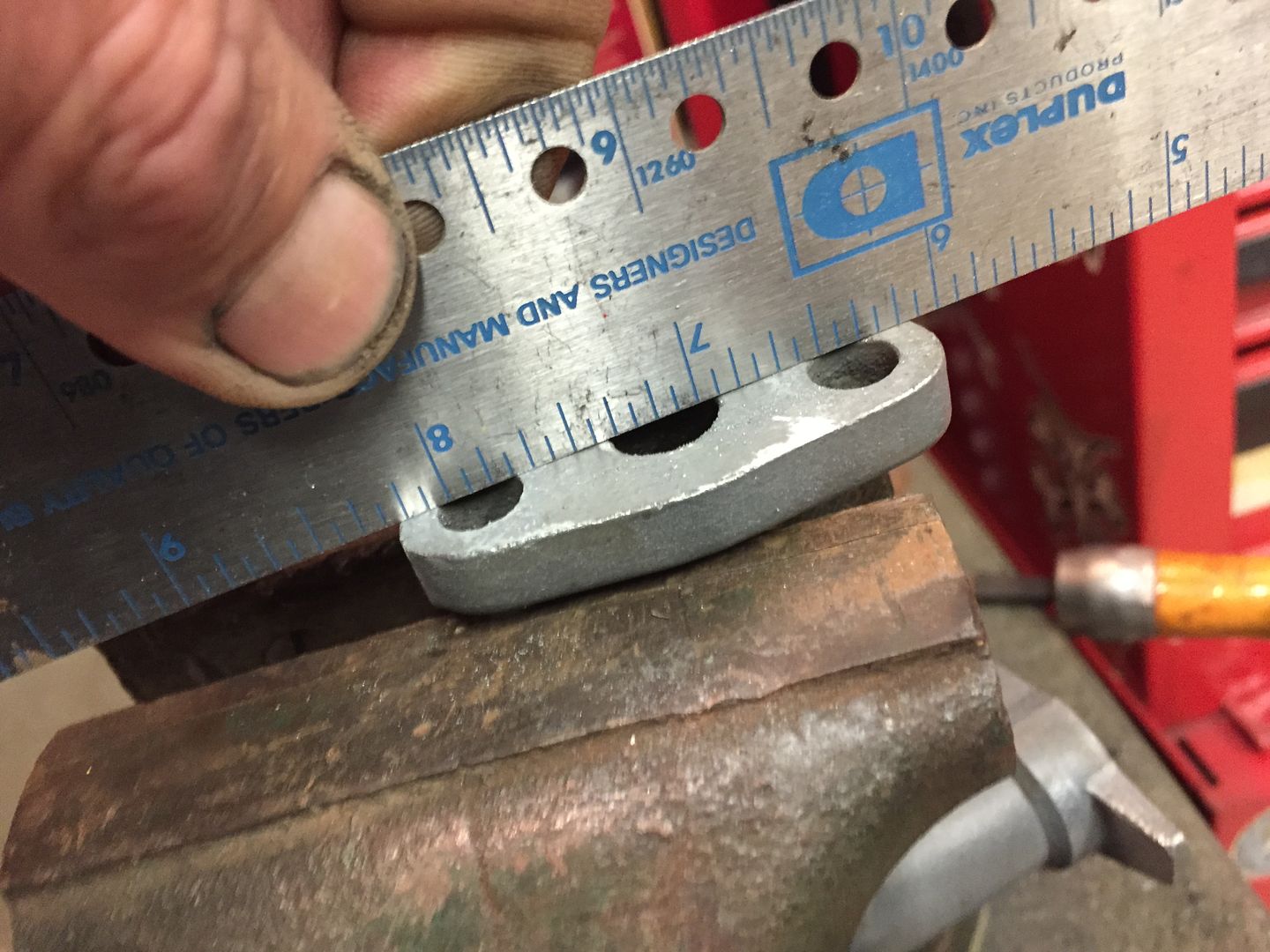 Use a fine file to square any high areas off. 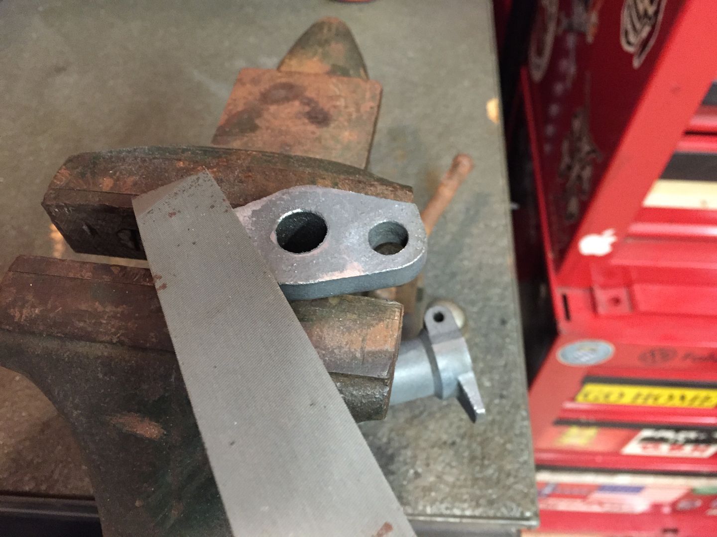 When finished a check for flat. Make sure to clean the tube thoroughly for any metal shavings created while filing. |
|
|
|
Post by Haines Garage on Jan 5, 2015 23:46:22 GMT -5
I now install the Timing Chain and Gears I am using A Richard Sanders Military Parts of Australia Double Roller. 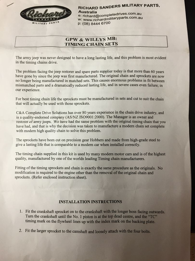 First Install the spacer ring on the camshaft face. 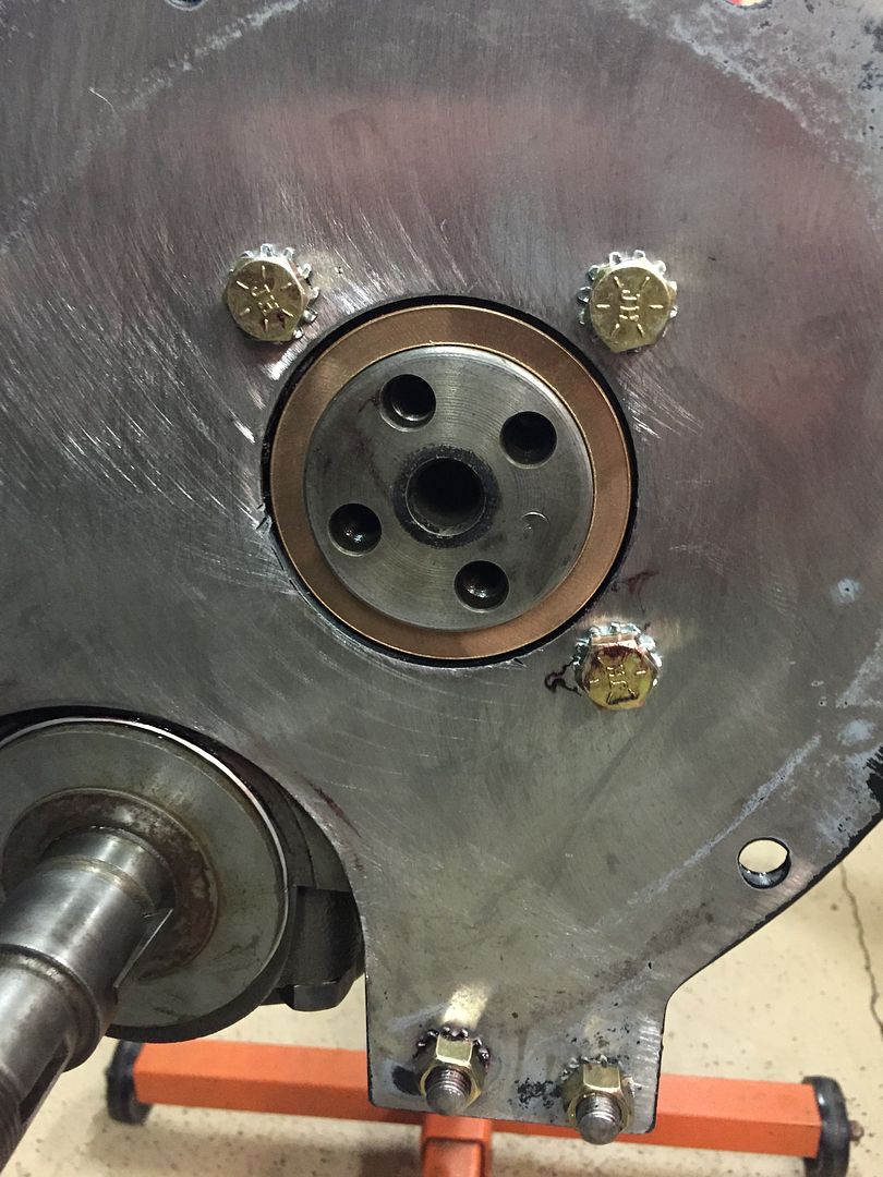 I coat the backside with assembly lube. I then install the lower gear. This gear is keyed into the Crankshaft. Line up the key before tapping into place. I used a socket that fit the diameter of the round face of the gear. 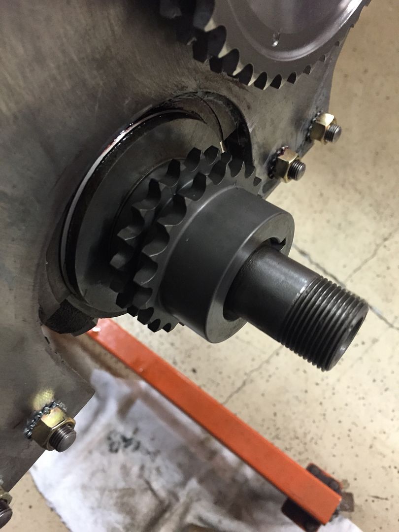 |
|
|
|
Post by Haines Garage on Jan 5, 2015 23:58:36 GMT -5
The Gear on the camshaft end has a bolt pattern that will only allow for its installation one way, Engine Piston #1 Is set at Top Dead Center. Camshaft has been set so that both valves, intake and exhaust are in the closed position. I install two of the bolts for the camshaft gear in order to align the two timing dots. 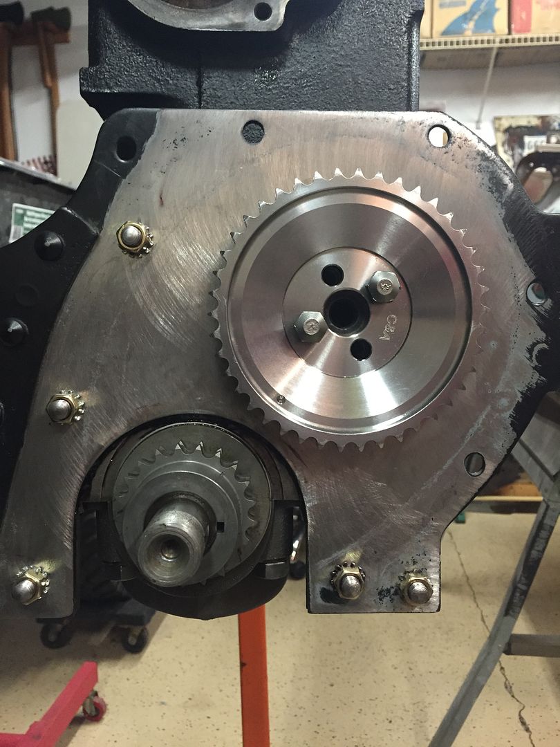 Look closely at the photograph. The two set dots are facing each other in a straight line. |
|
|
|
Post by Haines Garage on Jan 6, 2015 0:10:44 GMT -5
With timing marks aligned, I remove the timing gear and install the chain, I install on the crankshaft gear first, then slipping onto the Camshaft gear. The chain will only install one way correct to the bolt pattern on the Camshaft. It takes some moving on the gear to get it aligned correctly. Make sure when installing you keep the timing dots in line. Next install all four bolts and keepers. Some use star lock washers here, I choose to keep with OEM. 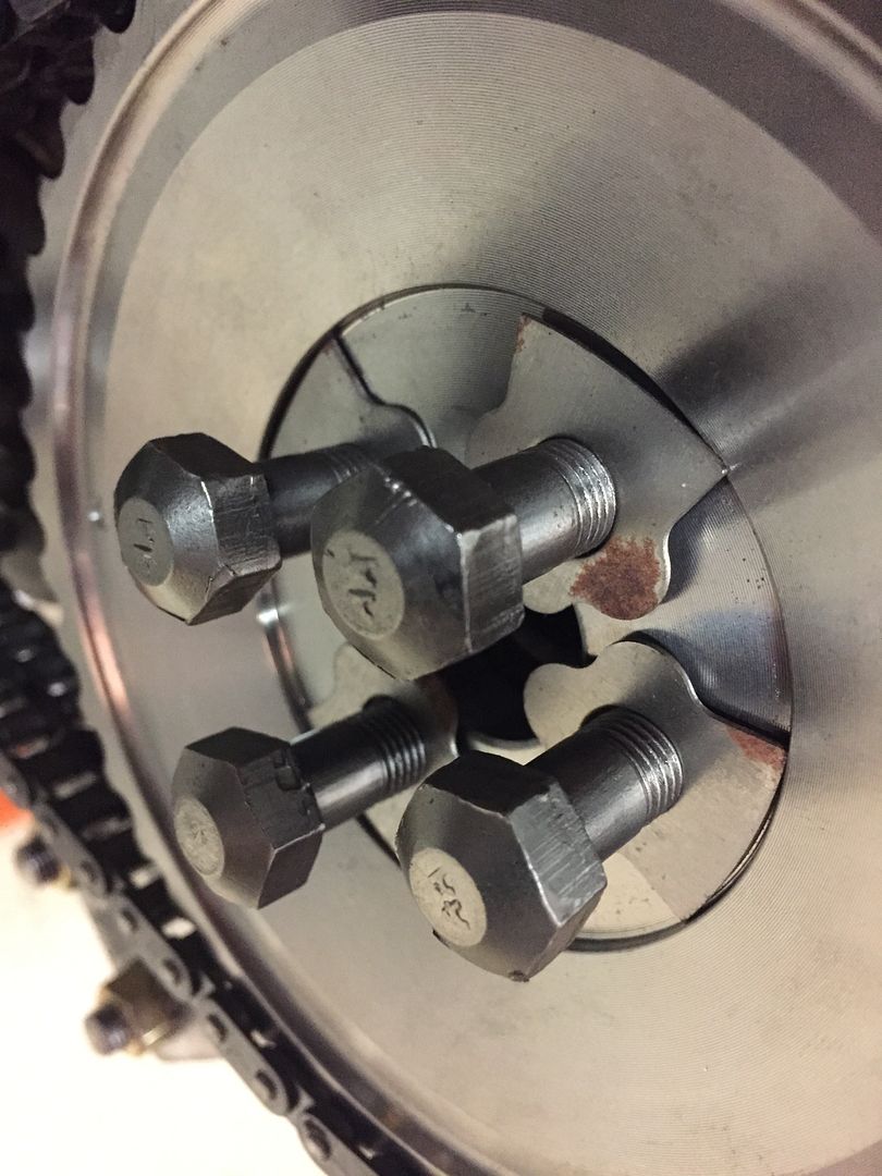 |
|
|
|
Post by Haines Garage on Jan 6, 2015 0:17:24 GMT -5
Torque Camshaft gear bolts to 40 Ft Pounds. Then using a small brass drift, bend the ears on the keepers in this fashion, 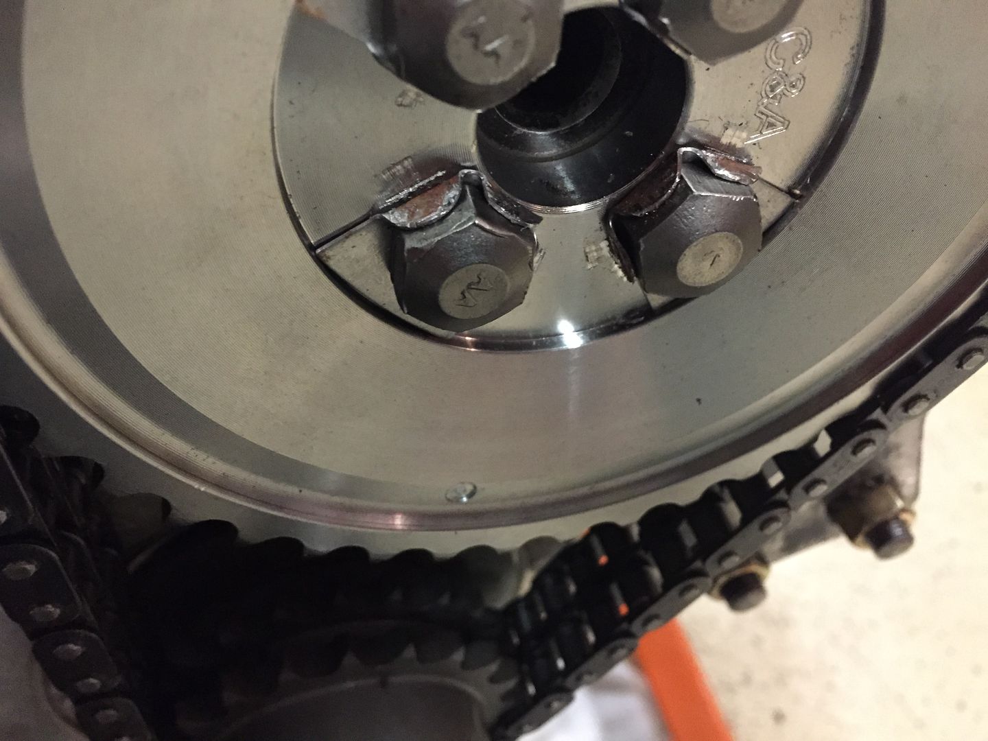 Install Oil Slinger 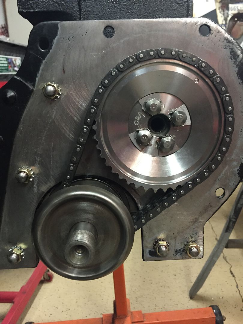 |
|
|
|
Post by Haines Garage on Jan 6, 2015 20:39:36 GMT -5
Insert the camshaft spring into the hole in the front of the camshaft. I had the original but purchased a new one. 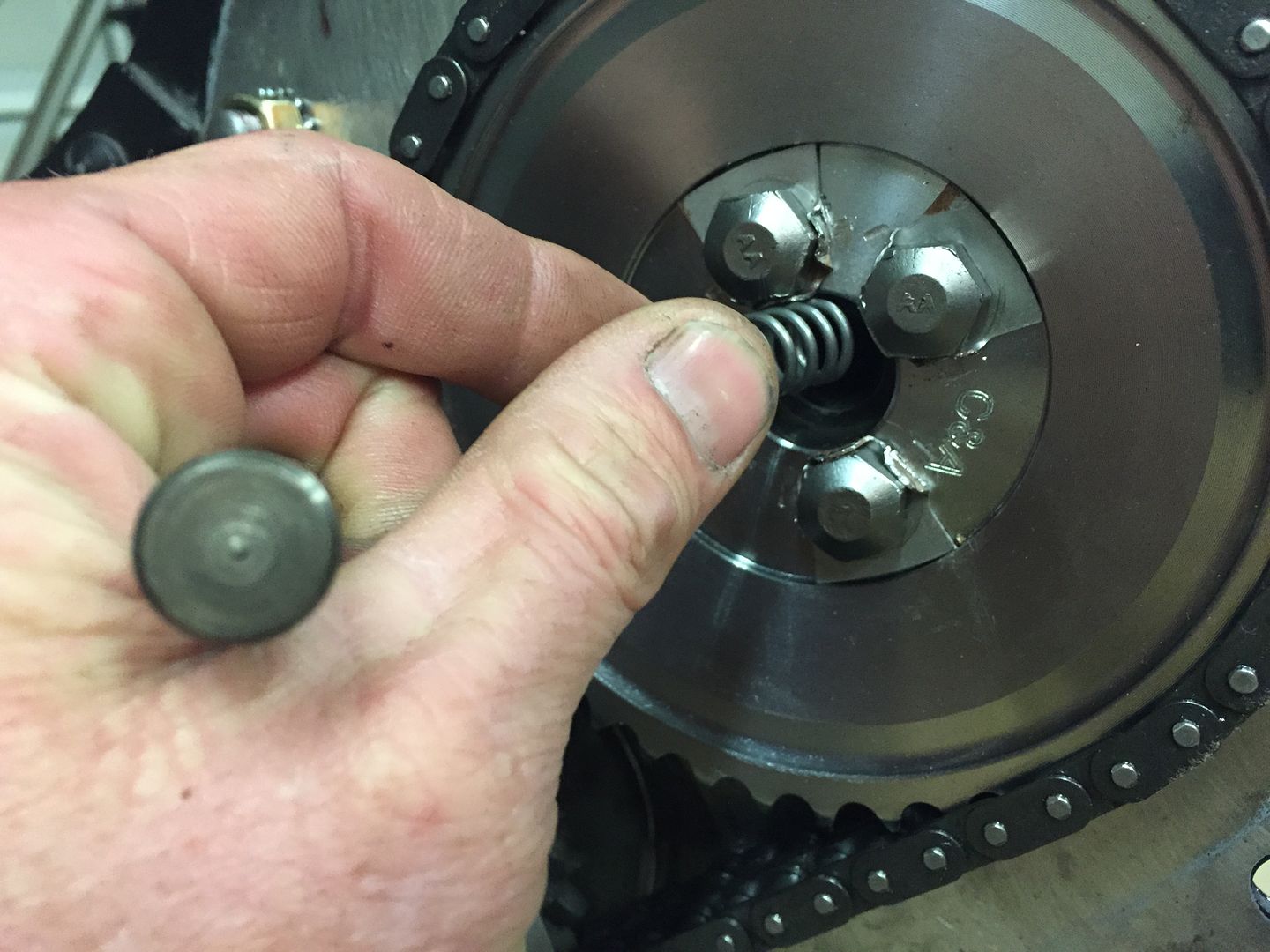 Then insert the pin. 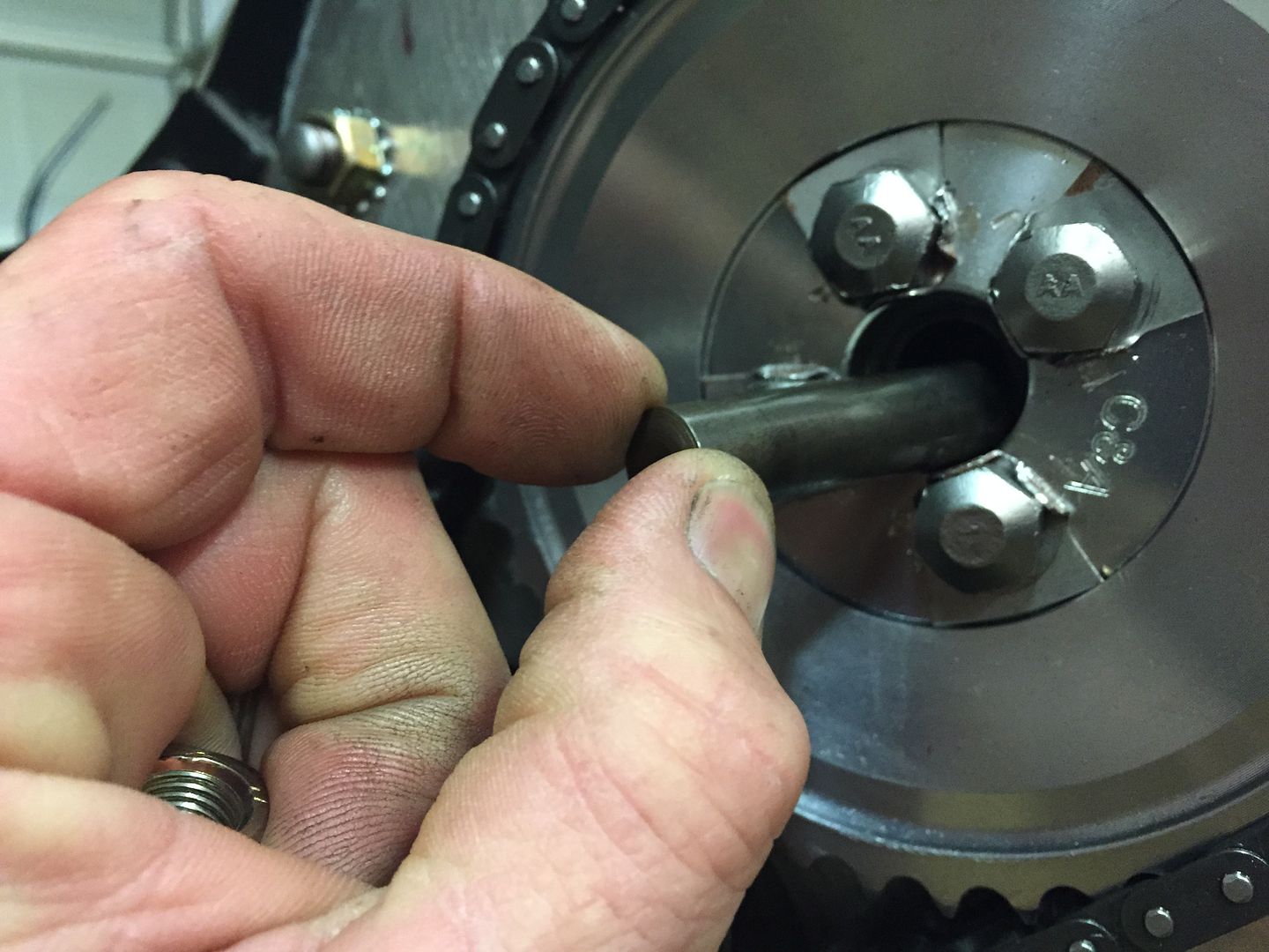 This assembly keeps proper placement of the camshaft. The timing cover, from the inside. Note the pin in the top of the photo. A gear drive engine does not have this pin. 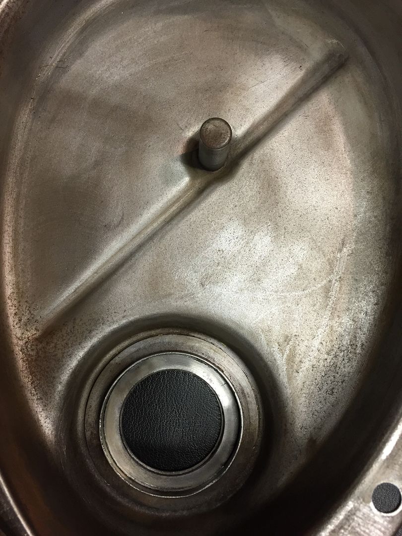 The bottom of the timing cover has a pressed on cap that sit into a cup integrated into the cover. These two pieces house the rope seal. Remove the cap with a small screw driver. Turn the blade on its side of the cap and twist. Move around the aps as you were opening a paint can. Be careful! do not deform or crease the cap. When it is removed, it looks like this. 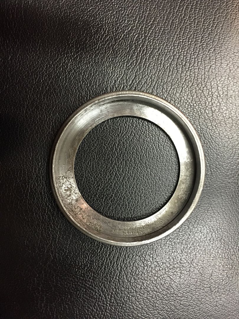 |
|
|
|
Post by Haines Garage on Jan 6, 2015 21:00:46 GMT -5
I decided to use a rope seal like the original would have been. There is a modern style rubber lip type that can be pressed into the cup. If you use the modern style, keep the cap. You may want it someday. I insert the rope seal into the cup. Position the joint in the seal in a twelve o'clock position when the cover is installed on the block. 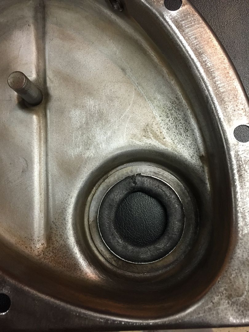 Install the cap with your fingers first by pressing. The lip of the cap should slide in without cutting into the seal. 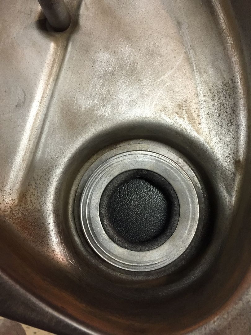 You can use a large socket that fits the perimeter of the cap, and a hammer to seat it. DO NOT OVER DRIVE IT. Tap until the cap seats. |
|
|
|
Post by Haines Garage on Jan 6, 2015 21:15:26 GMT -5
You will have to remove the nuts, and lock washers that were installed with the engine mounting plate to install the cover. Clean all mating surface one last time. Install a small amount of grease to the rope seal. Insert the Crankshaft Pulley into the rope seal. This will allow you to align the cover properly. I use Permetex #2 on the gasket, all sides. 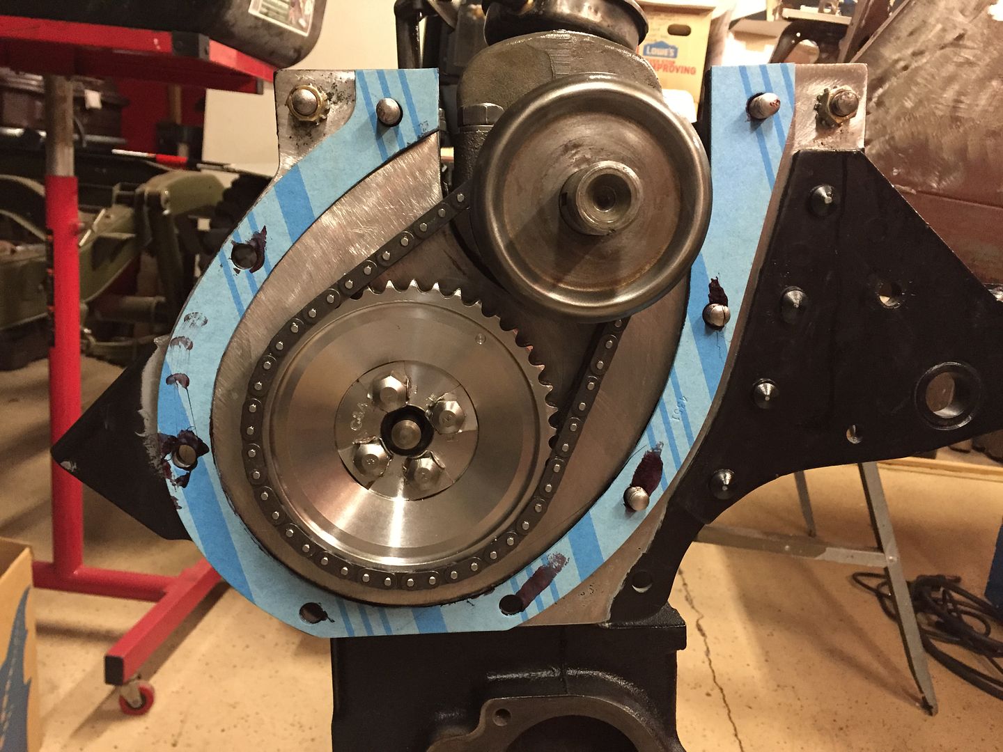 Install the cover, reinstall bolts and nuts, and torque to spec. 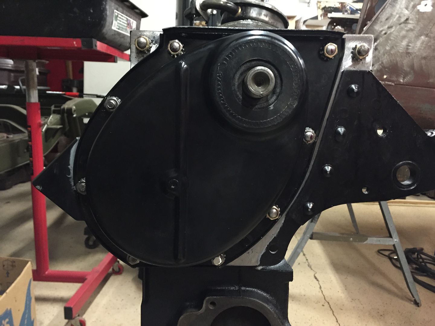 |
|
|
|
Post by Haines Garage on Jan 12, 2015 22:48:14 GMT -5
Installing the Oil Pan Before installing the actual oil pan gasket, the outside rubber seals are installed on the rear main cap. There are two sizes available. These must fit simply into the bore on the sides of the cap. Make sure you have the correct diameter. I apply a thin coat of Permetex #2. 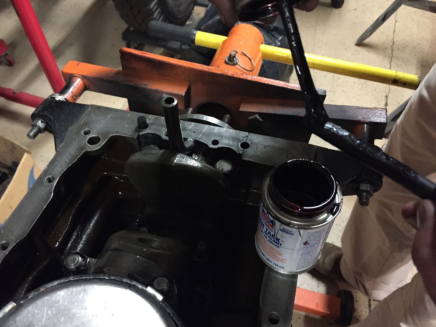 Then insert into the bore. The seals insert easily. When pushed into the bore, they will expand and seal. I apply a dab of Permetex to the top of the seal as well. 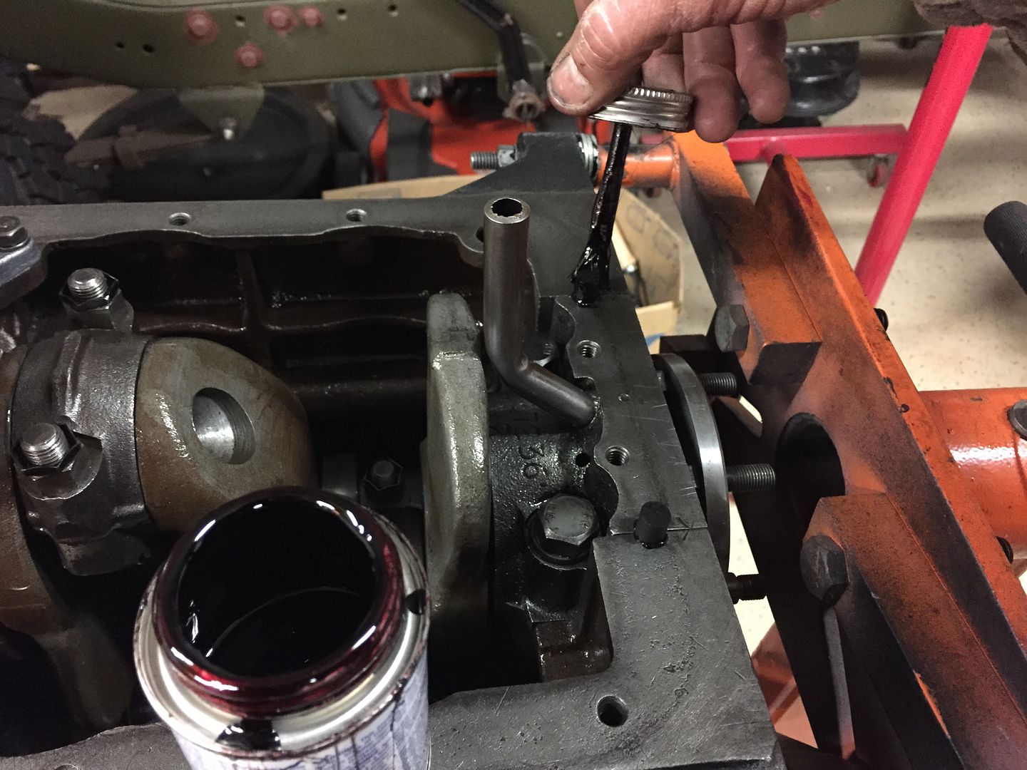 Apply gasket sealant to the block. A thin even coat. 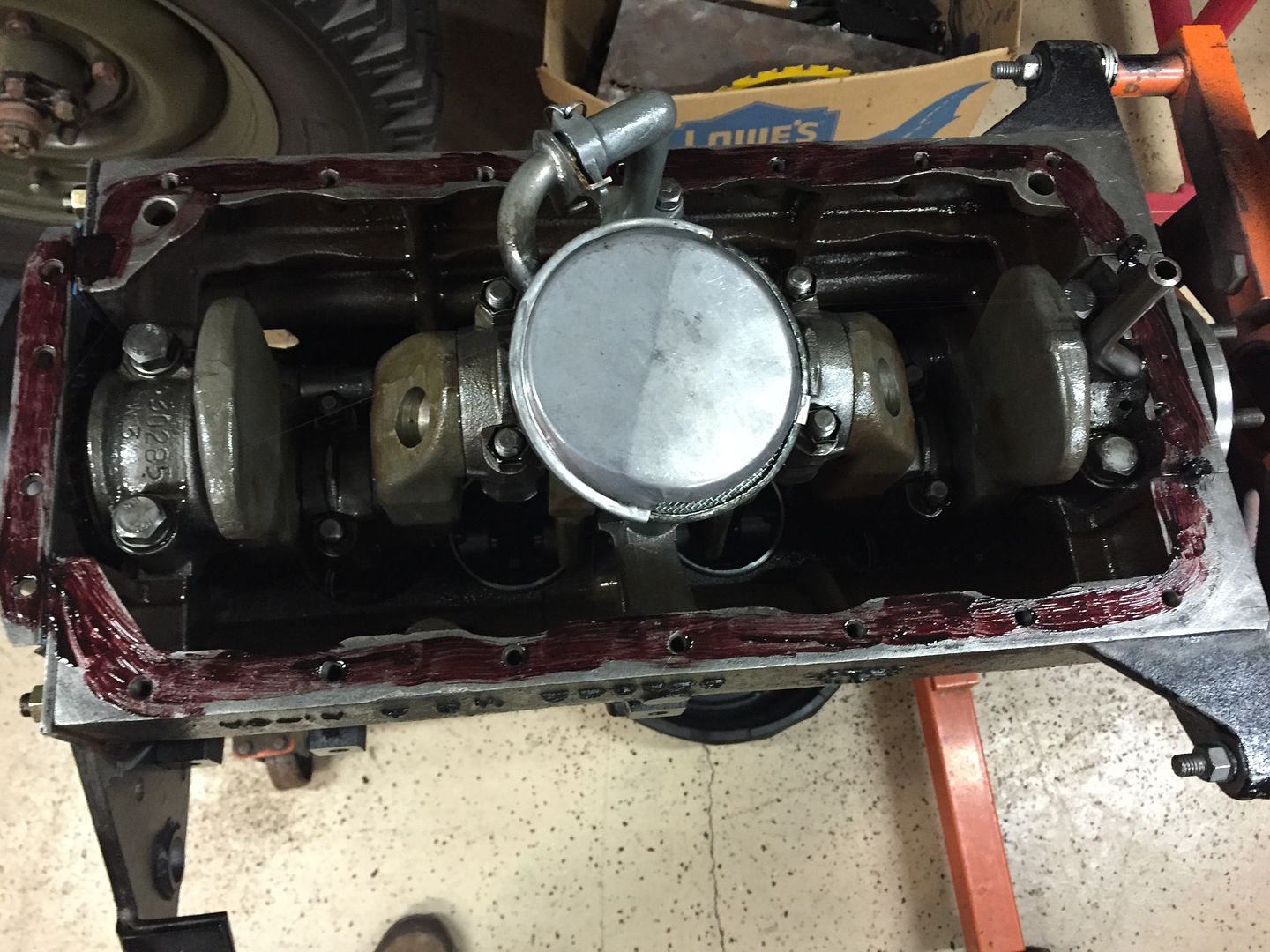 Install the oil pan gasket. Note the rear main cap seals. 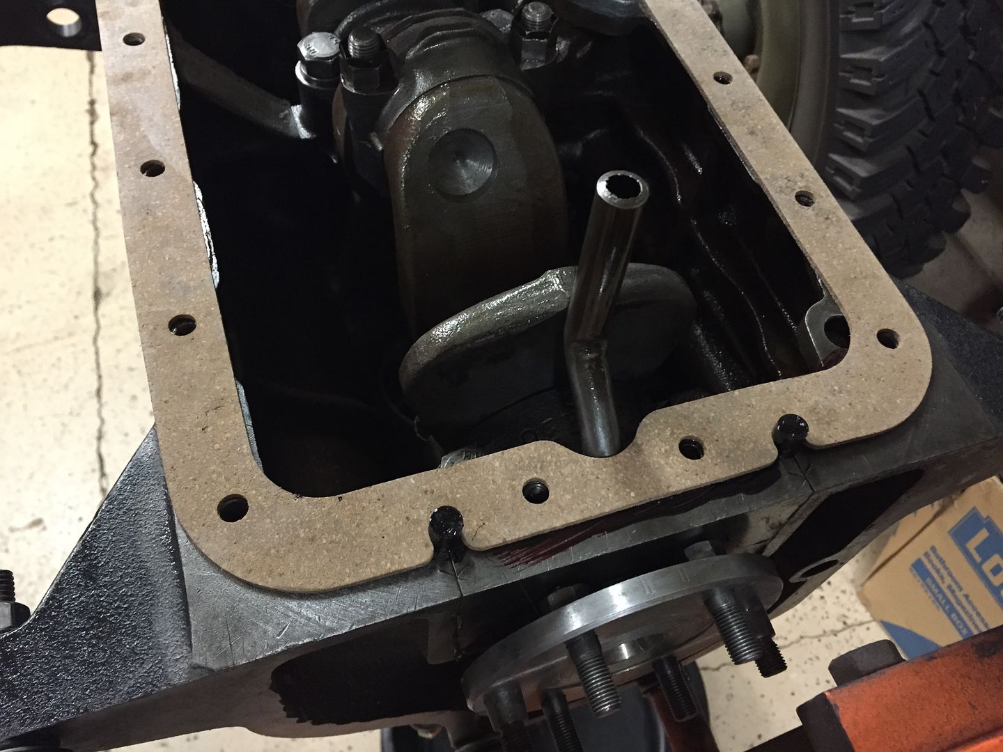 |
|