|
|
Post by Haines Garage on Dec 8, 2014 22:57:44 GMT -5
This engine was removed from a VEC Column Shift 1946 CJ2A. It is a Chain Drive L134 manufactured by Willys. Its casting #s are 638632 W5A NI-0R.
The Block was disassembled, and taken to a machine shop. A crack was found between the #2 and #3 Cylinders.
Block was hot tanked, crack welded and repaired, decked, bored .40 over in the cylinders, Crank was ground .20 under. The head was milled, and the valve guides removed and replaced. The valve seats were ground. The connecting rods were resized.
The block was scrubbed clean, primed and painted with high temp engine enamel.
Here is how I rebuilt it....
|
|
|
|
Post by Haines Garage on Dec 9, 2014 23:01:34 GMT -5
When I received my block back from the machine shop, I knew it had to be cleaned further, hot tanking gets most, but not all deposits in the water jackets. Using brass cleaning brushes, I cleaned all areas that could be reached, washing the block out with degreaser, then using compressed air to dry it. I masked off all orifices, then primed and painted the block with Duplicolor Engine Enamel.
|
|
|
|
Post by Haines Garage on Dec 9, 2014 23:11:58 GMT -5
When I received my block back from the machine shop, I knew it had to be cleaned further, hot tanking gets most, but not all deposits in the water jackets. Using brass cleaning brushes, I cleaned all areas that could be reached, washing the block out with degreaser, then using compressed air to dry it. I masked off all orifices, then primed and painted the block with Duplicolor Engine Enamel.
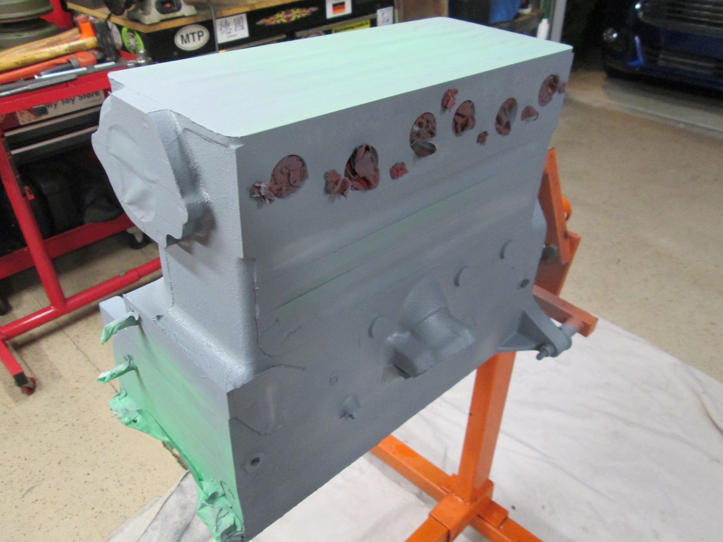
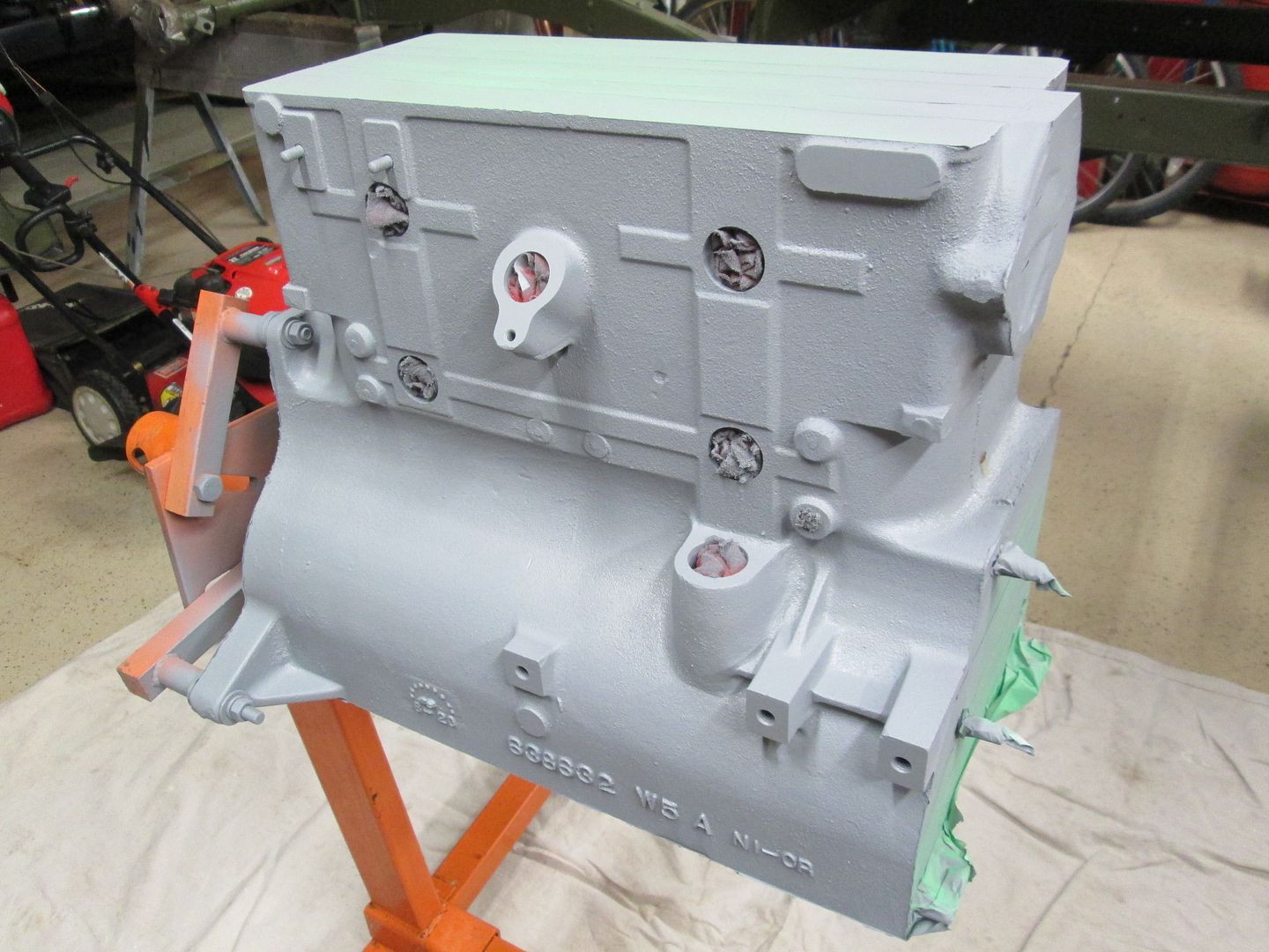

![]()
![]()
|
|
|
|
Post by Haines Garage on Dec 10, 2014 19:34:04 GMT -5
Some other important preparations that were made is that all the threaded areas in the block were chased with a Tap this will insure clean threads for the new studs, and bolts.
Let's begin!
|
|
|
|
Post by Haines Garage on Dec 10, 2014 19:38:29 GMT -5
The first thing to do is clean out the oil galley. To do so you must remove the front and rear plugs. There is a square slot on the plugs. I removed mine but making a tool out of a 3/8 socket drive extension. I ground it a little at a time until it fit square.   |
|
|
|
Post by Haines Garage on Dec 10, 2014 19:48:06 GMT -5
After I removed the front an rear plugs, I used a gun cleaning rod and patches cut from an old shirt to clean the oil galley. Patches were alternated with on soaked in lacquer thinner , and then clean. I repeated the process until the clean patch indeed came out clean!   Once I was satisfied on the clean galley, I cleaned the plugs on a fine brass wire wheel, and installed them. I coated the threads with permetex #2 before installation. |
|
|
|
Post by Haines Garage on Dec 10, 2014 20:07:04 GMT -5
The next step is to install new Freeze Plugs. The originals were removed by the machine shop prior to hot tanking. On the L134 chain drive engine, there are 5, 1 1/4 plugs on the block, and 1, 1 3/4 for the rear of the cam shaft. The are the concave disc type. I had ordered a brass set, that came with 4 small and one large, as per engine. I bought a steel 1 1/4 from a local parts shop. The only reason I mention this, is that there is a different feel installing the two different metals. The brass is more malleable, I used a brass drift to first strike the center, and then work the other areas surrounding inward. My brass plugs are almost, but not quite flat. The steel plug, I dimpled the center, then set it with a socket, about the size of the opening. The steel in my opinion set harder. With more effort. I cleaned all the plug openings in the block with lacquer thinner prior to plug installation. Then applied a film of permetex #2 to the opening, and the outside radius of the plug. After the plug was set, I cleaned the surfaces off with lacquer thinner.     This was done with the engine, NOT on a stand. To reach the galley plugs, and Cam Freeze Plug would almost impossible. After these items were installed, the block was mounted to a stand. |
|
|
|
Post by Haines Garage on Dec 10, 2014 20:54:51 GMT -5
I had the machine shop remove the old, and install new valve guides. They also ground the valve seats, and decked my ribbed head. The chain drive engine has a non ribbed head. I know this. This head was removed from my Grandfathers original 1946 gear driven engine. The only head, out of SEVEN I have had that were not cracked. 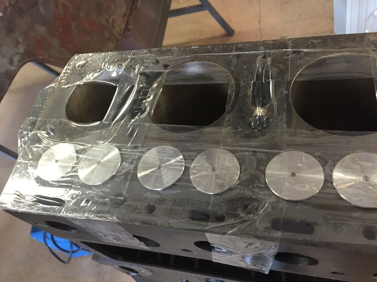 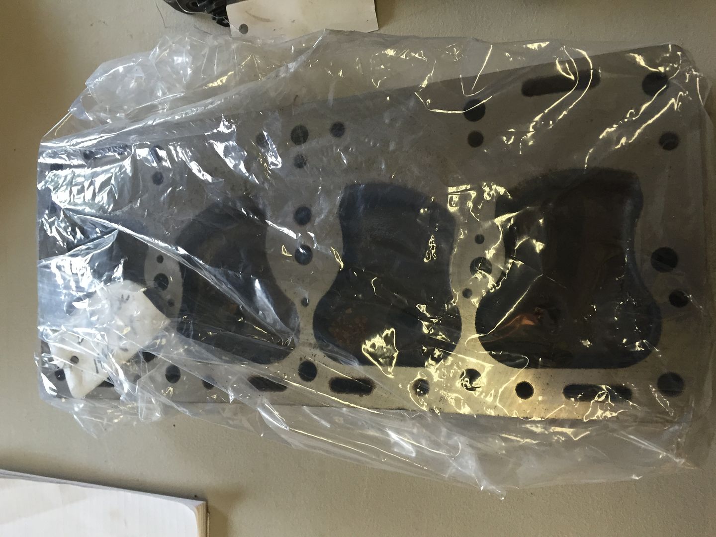 I also had the connecting rods resized. This is a process in which the machine shop removes a small amount of material from the mating face of the cap, and then mills the area that connects the rod to the crankshaft, round again. This step was almost overlooked. Glad I had it done! 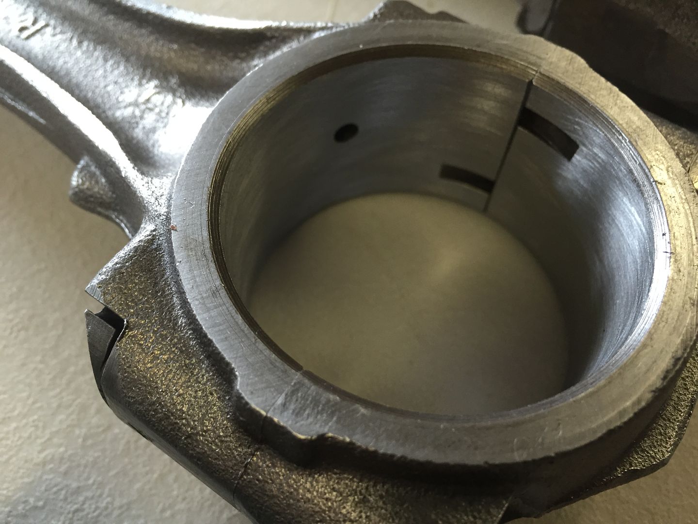 |
|
|
|
Post by Haines Garage on Dec 10, 2014 21:06:07 GMT -5
Valve Train To make it easy to install the tappets, I tagged and removed the new valves from the block. I am using the original tappets that I removed from the engine. Tappets were cleaned with the threaded piece removed, lubed, and then numbered to be replaced to their original locations in the block. 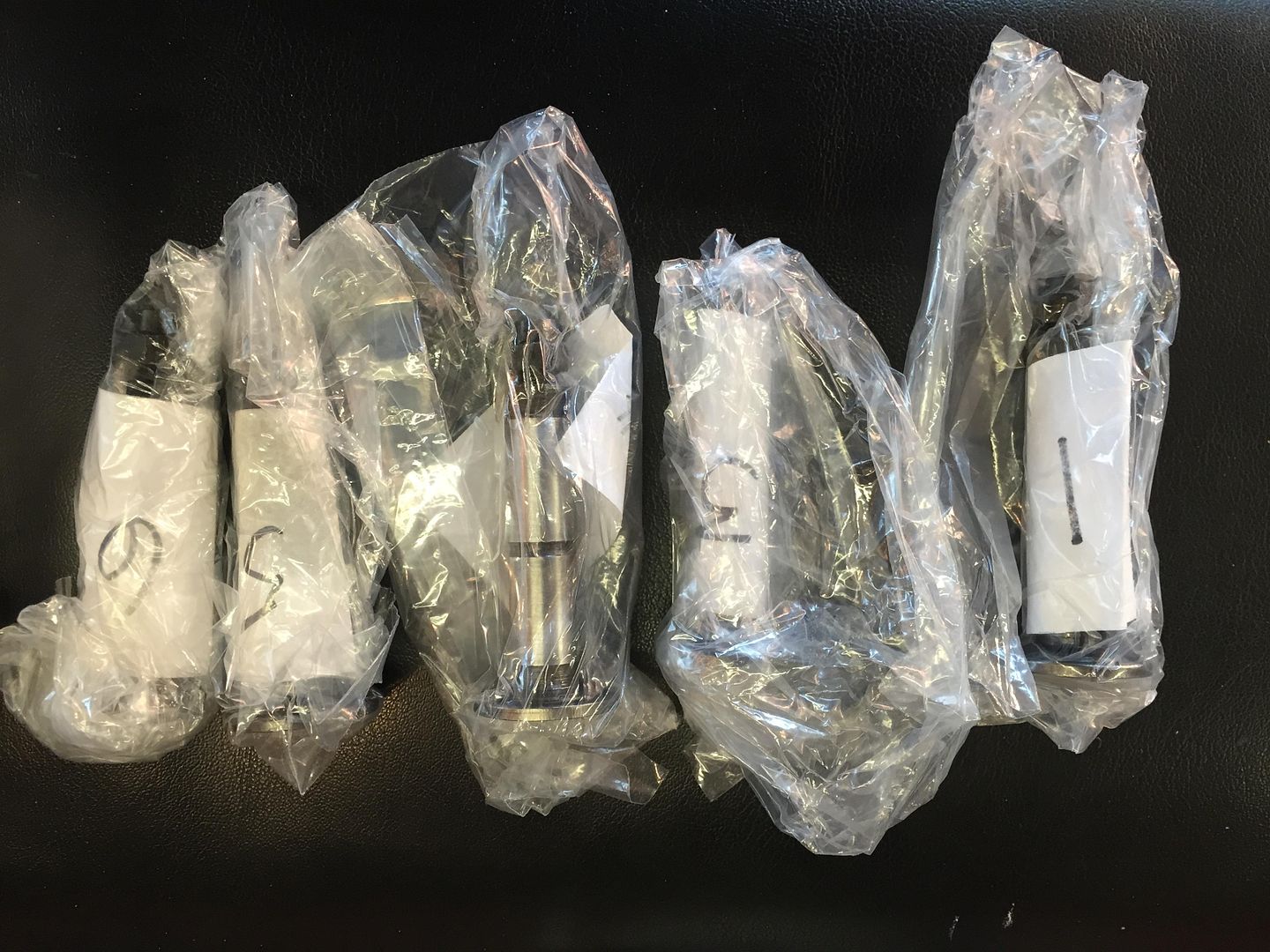 Before installing the tappet, coat the surface with assembly lube. A thin even coat. I spin them slowly into position to insure even lubrication. 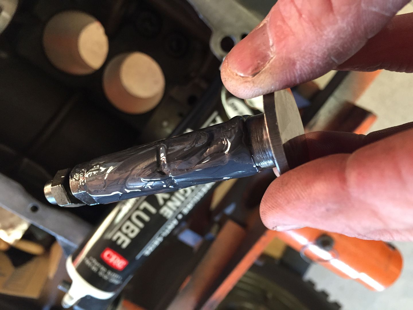 After all the tappets are replaced, I apply a dab of assembly lube to the cam surface, and even it out with a finger. 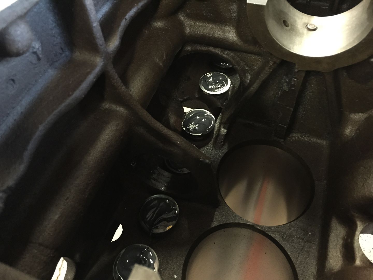 Tappets installed. |
|
|
|
Post by Haines Garage on Dec 10, 2014 21:32:36 GMT -5
The camshaft is not difficult to install, but you need to be patient and careful. A new bearing was installed by the machine shop for me. The oil hole in the bearing must line up properly with the oil hole in the block. VERY IMPORTANT! I tested my alignment with an air hole, and a straight pipe cleaner. I lubed the front bearing and the camshaft " Rounds", spots riding on the castings in the block. 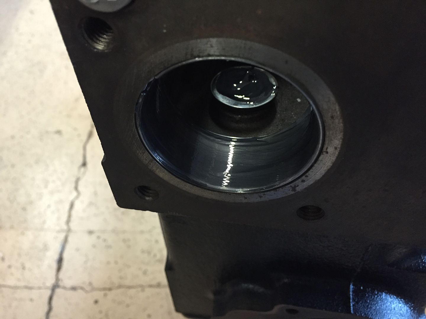 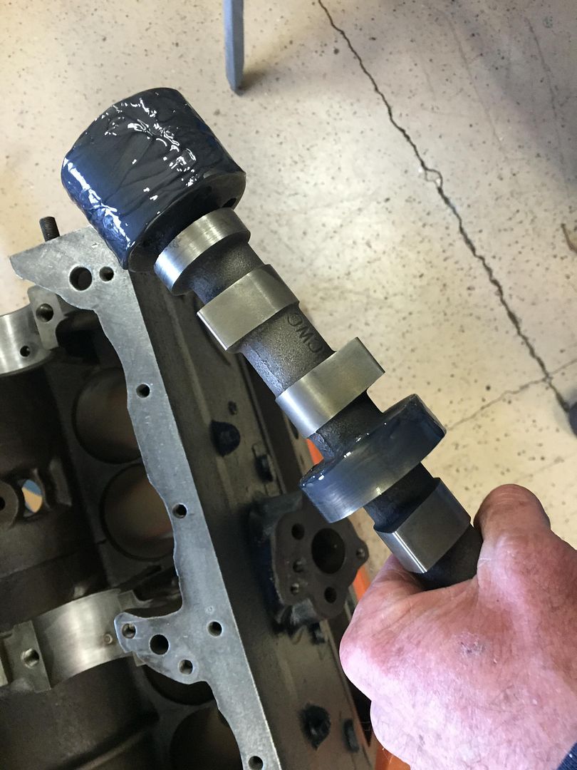 When you install the camshaft, use two hands, be sure no to nick or scratch the bearing. Move slow, and purposefully. Like you were playing the old game "Operation". It goes right in. I spin the cam slowly to feel for any binding, and to smooth out the assembly lube. 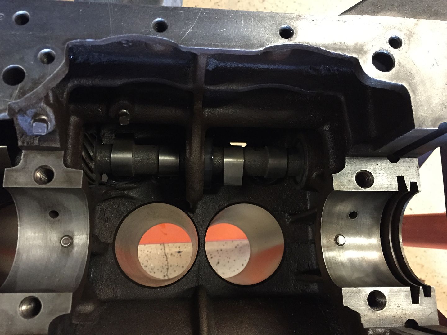 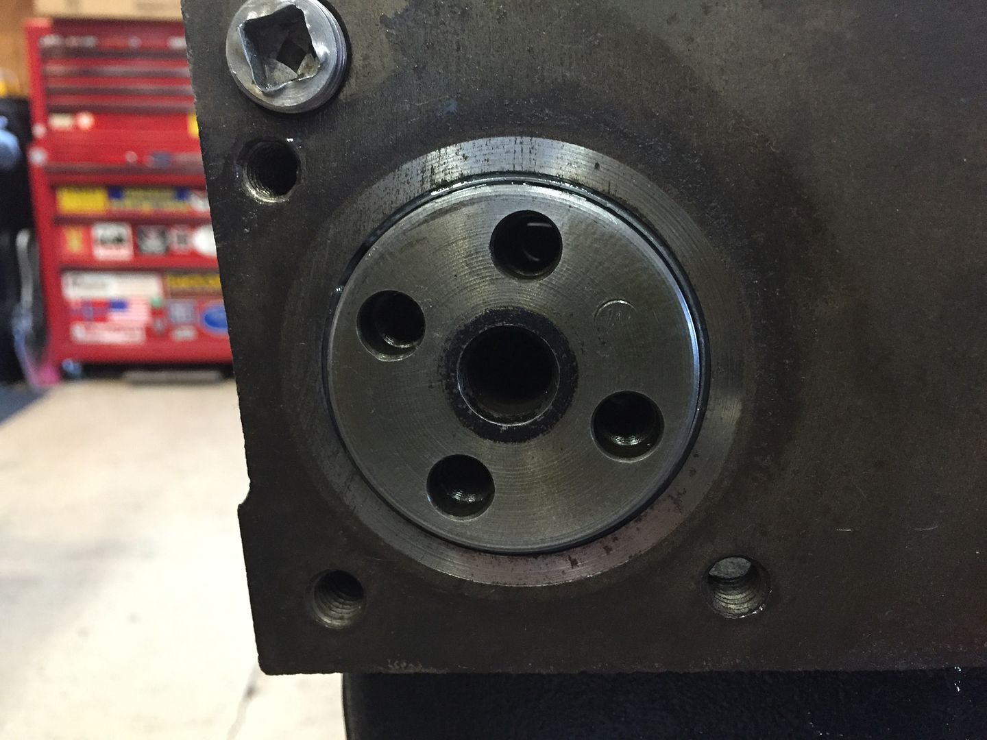 Notice the offset of gear mounting bolt areas on the front of the camshaft. |
|
|
|
Post by Haines Garage on Dec 10, 2014 22:11:09 GMT -5
Flipping the engine upright on the stand, It is time to install the valve springs, valve spring retainers, and lock retainers. I have installed the old gear on the cam to be able to spin the cam to lower and raise the tappets. 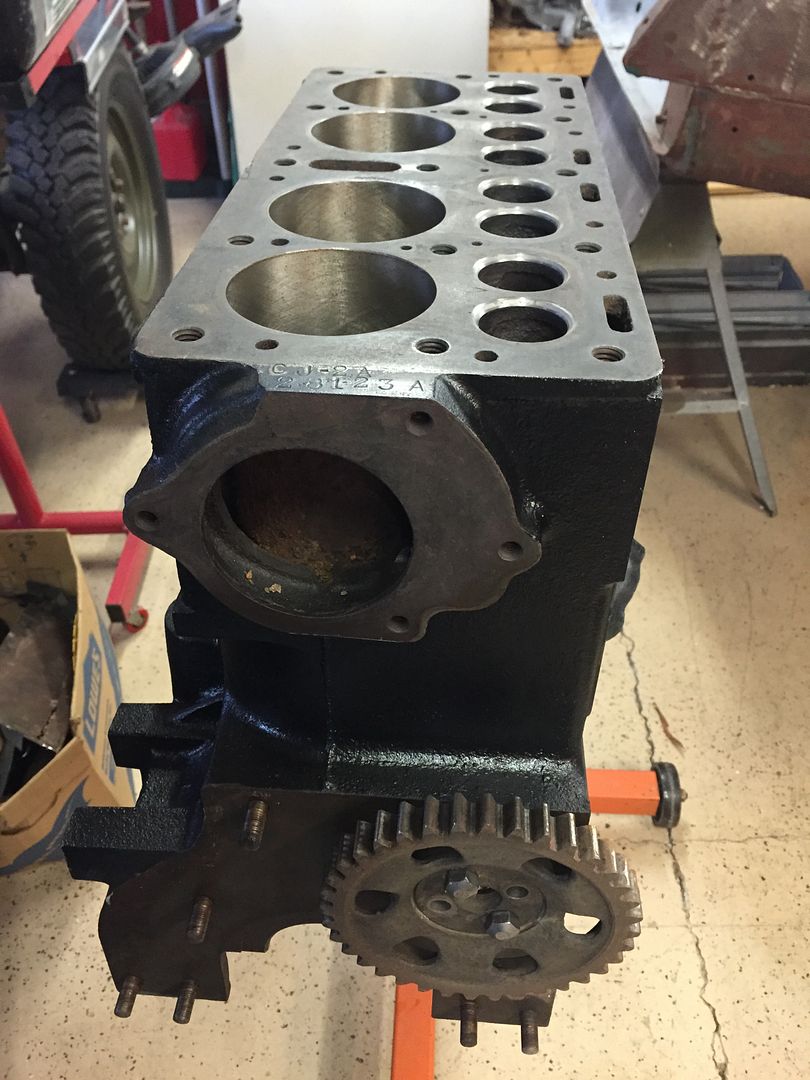 I insert a valve spring retainer into the loose wound side of the spring. SPRINGS ARE INSTALLED TIGHT WOUND SIZE TO THE BLOCK. Push the spring into its location and over the tappet. This can be done by using two thumbs, if not, use a screw driver to carefully lever the spring into place. I install all springs and valve spring retainers. Working one at a time, replacing the valves in their correct positions as I go. Now the fun part, replacing the lock retainers. Using a Vintage Sunney spring compression tool, I compress the spring to reveal the cut outs in the valve for the lock retainers. 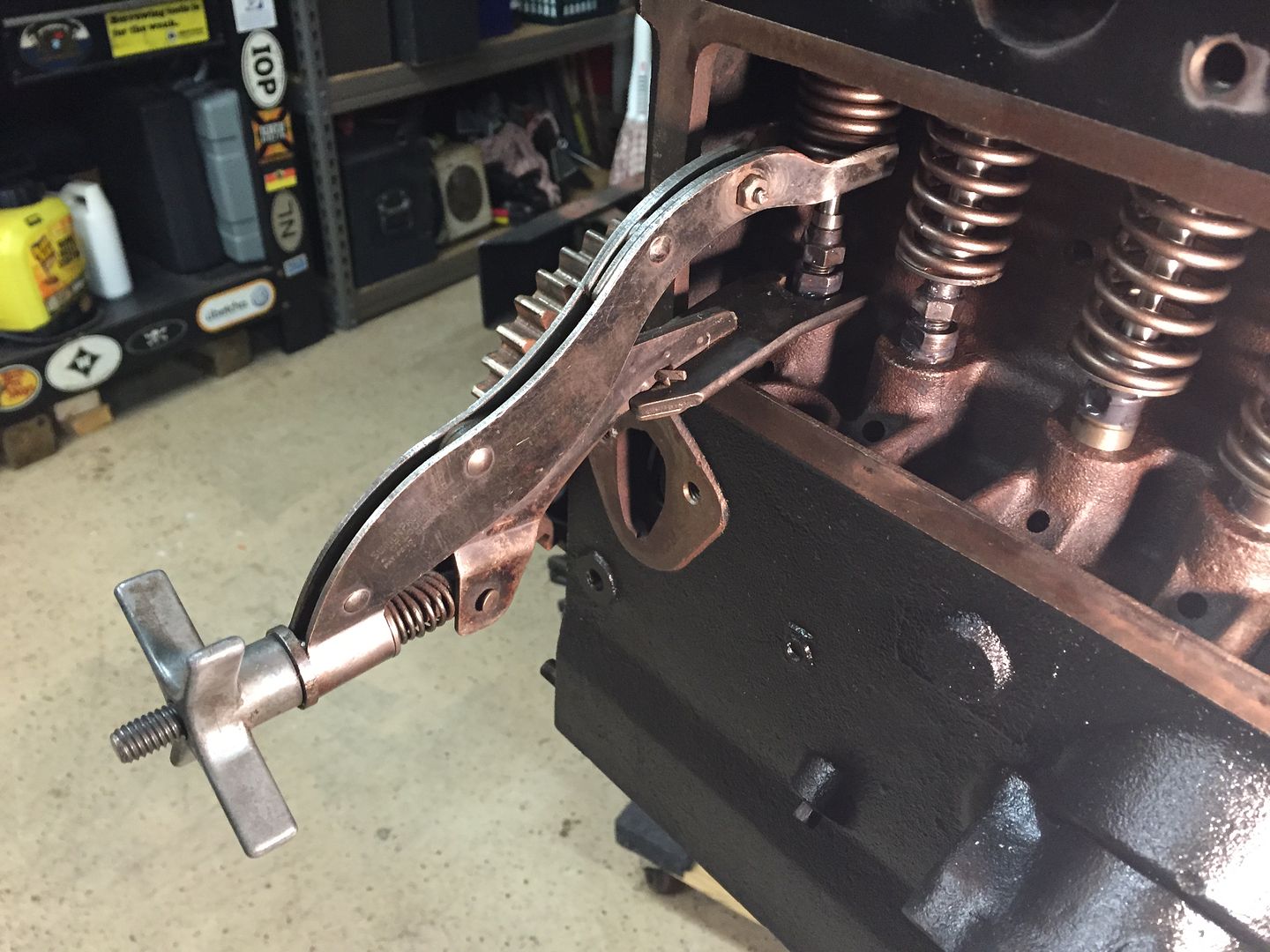 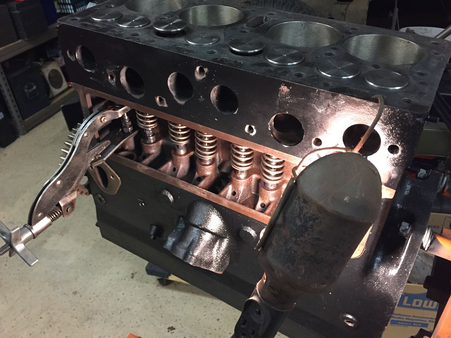 Using a small dab of grease to hold the lock retainer in place on the valve, I install them buy hand. The tapered (shorter) end of the retainer goes toward the top of the engine. 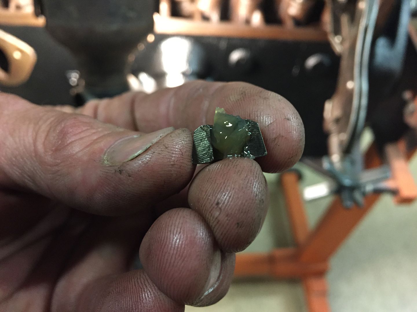 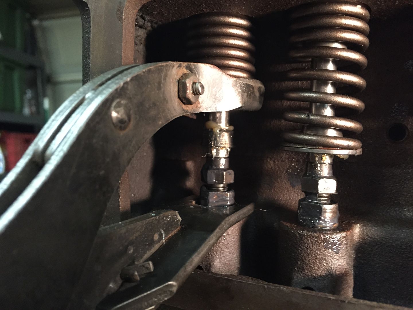 Working left to right on the block, I install all of the lock retainers. Using the spring tool, when you lower the spring, go slow and smooth so that the keepers seat properly. You must rotate the camshaft, so that the tappet on the valve you are working on is at its lowest position, and the valve must be removed. |
|
|
|
Post by Haines Garage on Dec 12, 2014 0:08:37 GMT -5
Valve and Springs Installed 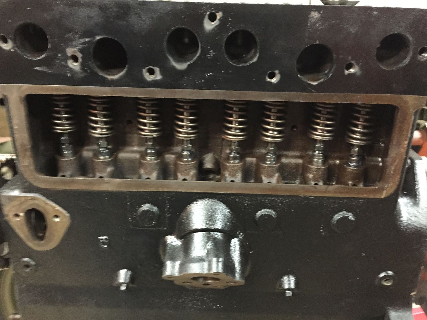 |
|
|
|
Post by Haines Garage on Dec 12, 2014 0:33:27 GMT -5
The next assembly to install is the Crankshaft. This includes the Pistons and Ring Sets. I prepare the pistons in the following order. The pistons are made up of the following things. A connecting rod. (Connecting Rods are from front to back of engine, 1234. No.1 and No.3 are the same, and No. 2 and No.4 are the same.) these rods have different bearing keepers, that will be shown at the end of this post. The similar, 1 and 3, and 2 and 4 are interchangeable.)I did not mean to confuse by stating this. In a lot of engines, the connecting rods will have a some point been individually replaced. When you disassemble your engine, be sure to make a mark of your own with a punch prick, or something that will not wear off. Connecting rod order is critical. Mine removed on this engine were from front of engine to back, stamped 1 2 3 4. A Piston. The actual cylindrical piece that fits in the bore of the block. Pistons are matched to your machine work. Standard. .20 .40 .60 oversized. Be sure to match your pistons to the machine shop specs. A Pin (Wrist Pin) the pin that connects the connecting rod to the piston. Here is a diagram from the Willys Parts Manual 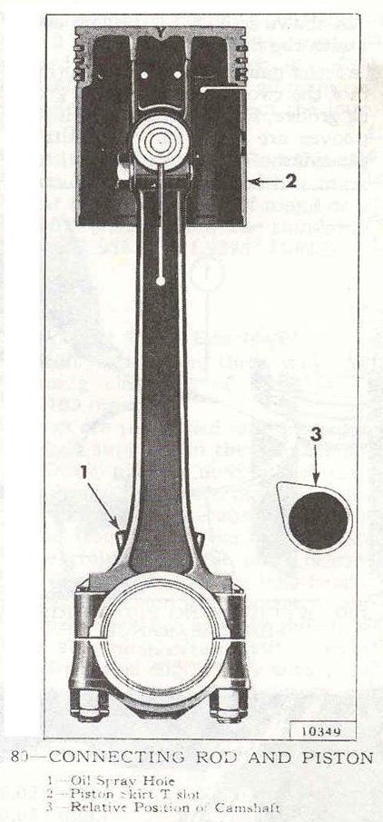 Note the position of the oil squirt hole, and the T slot on the Piston. THIS IS VERY IMPORTANT TO PISTON INSTALLATION! The T slot is placed on the opposite side of the oil squirt hole. 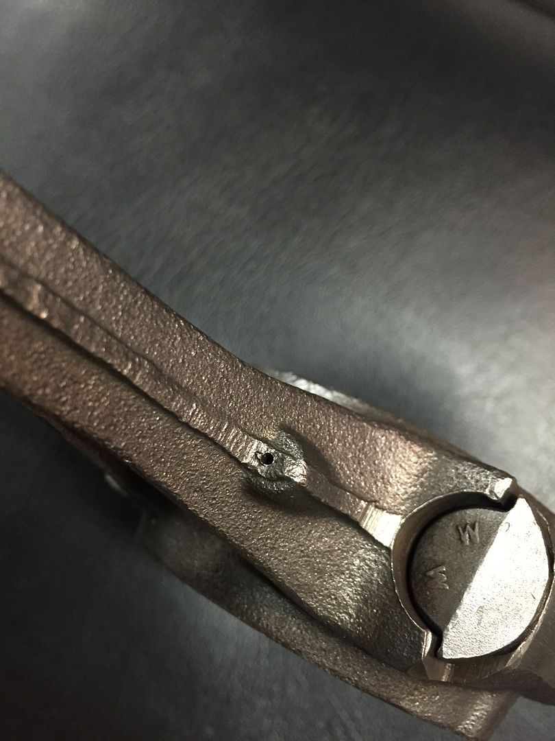 Squirt Hole 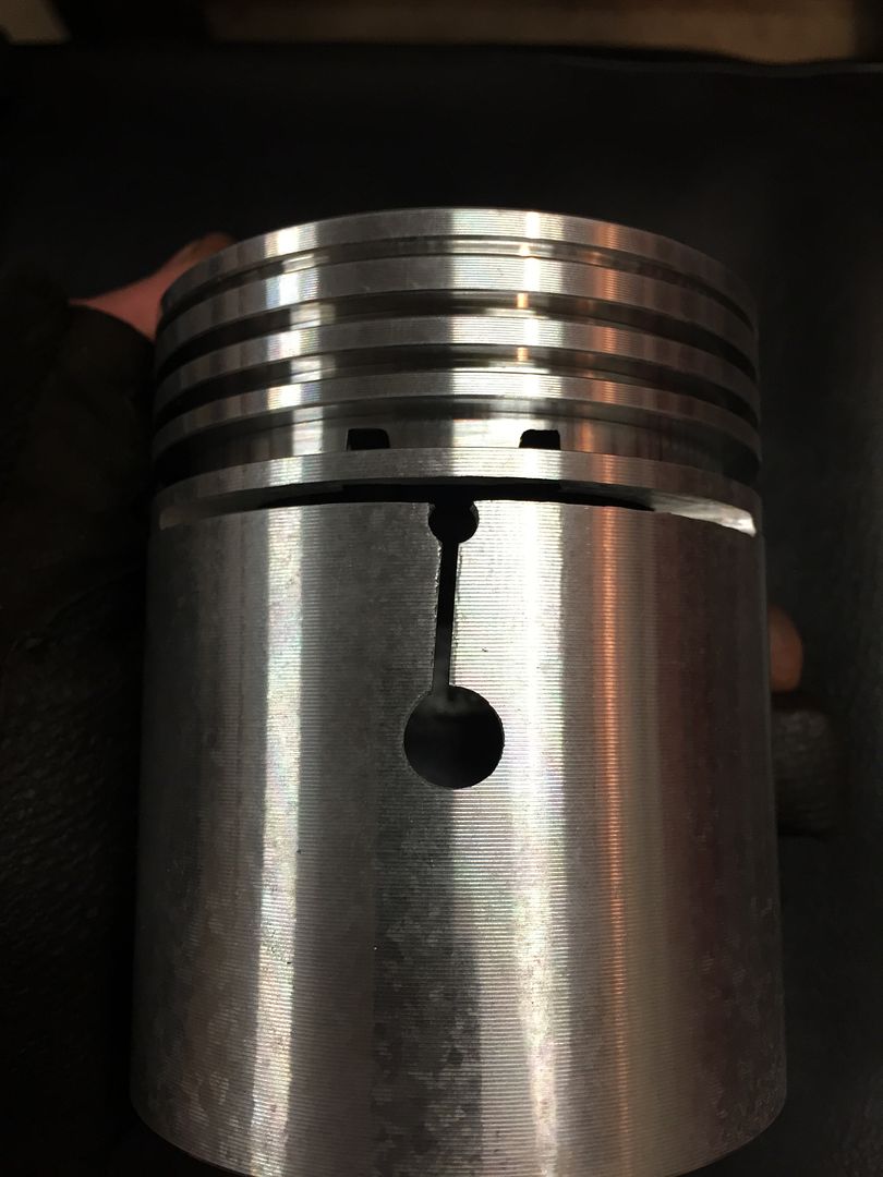 Piston showing T Slot 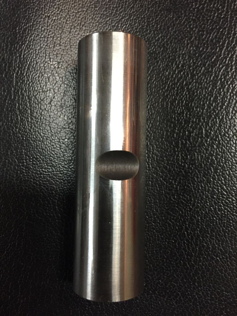 Pin showing bolt slot THIS IS IMPORTANT |
|
|
|
Post by Haines Garage on Dec 12, 2014 0:45:49 GMT -5
All of the original Connecting Rods have been resized from the machine shop. I cleaned them thoroughly with a fine brass wire wheel. I cleaned the oil squirt hole with a wire, and check it twice. Before attempting installation, I chased the threads on the connecting rods with a 3/8 x 24 tap. 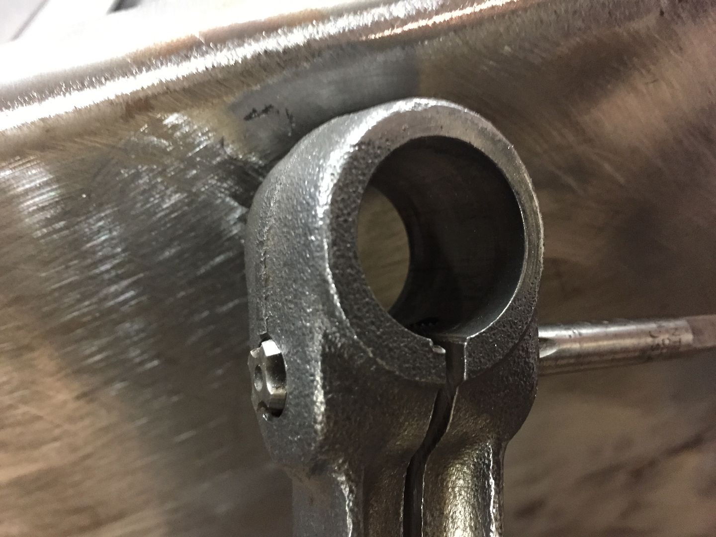 This will make installation of the bolt easier, and make for setting the bolts secure. 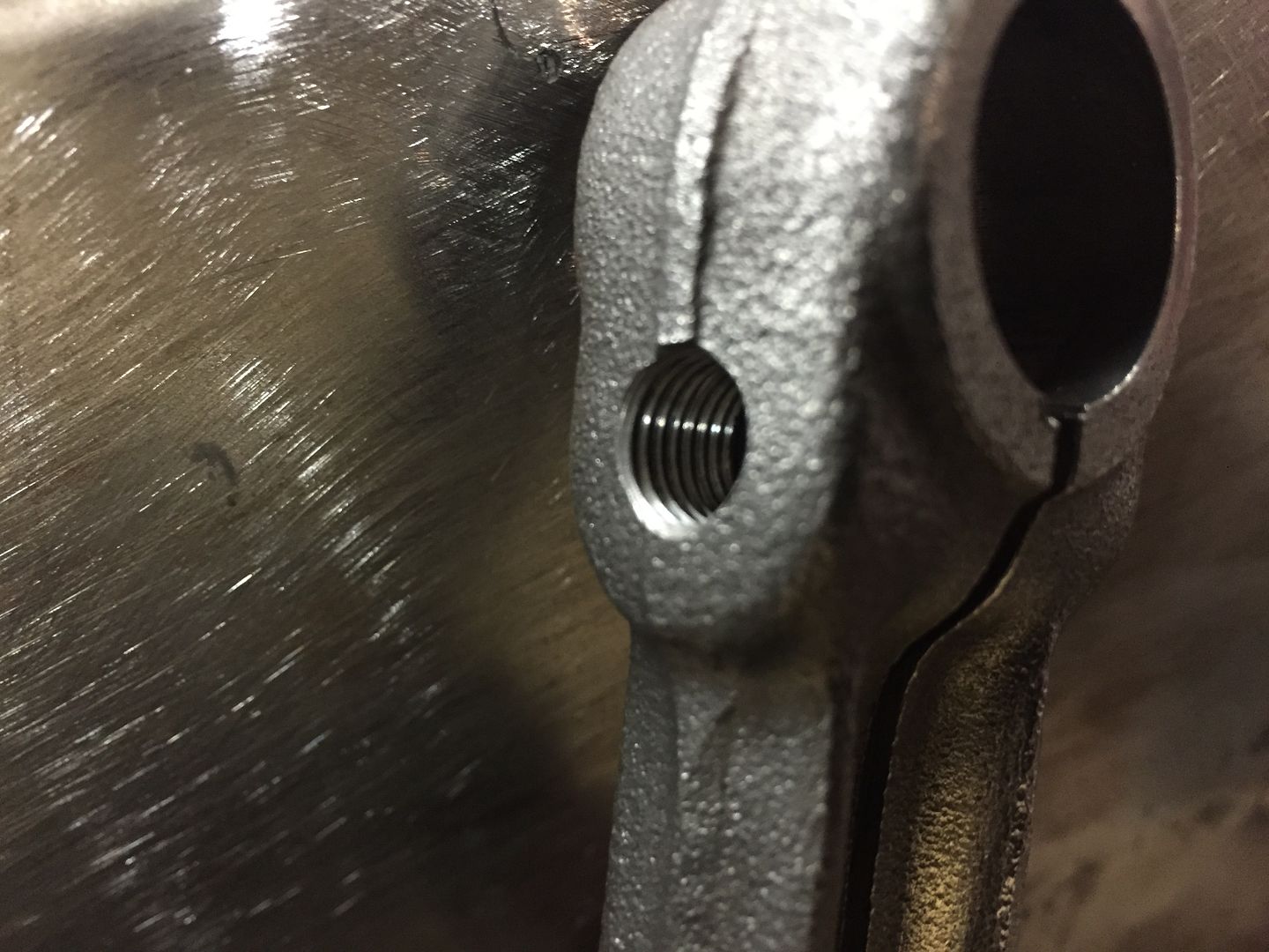 I clean and wire wheel all of the set bolts, and lock washers. I find one that is damaged. Lucky for me I have a set of connecting rods that have the original bolts. They are marked AE. 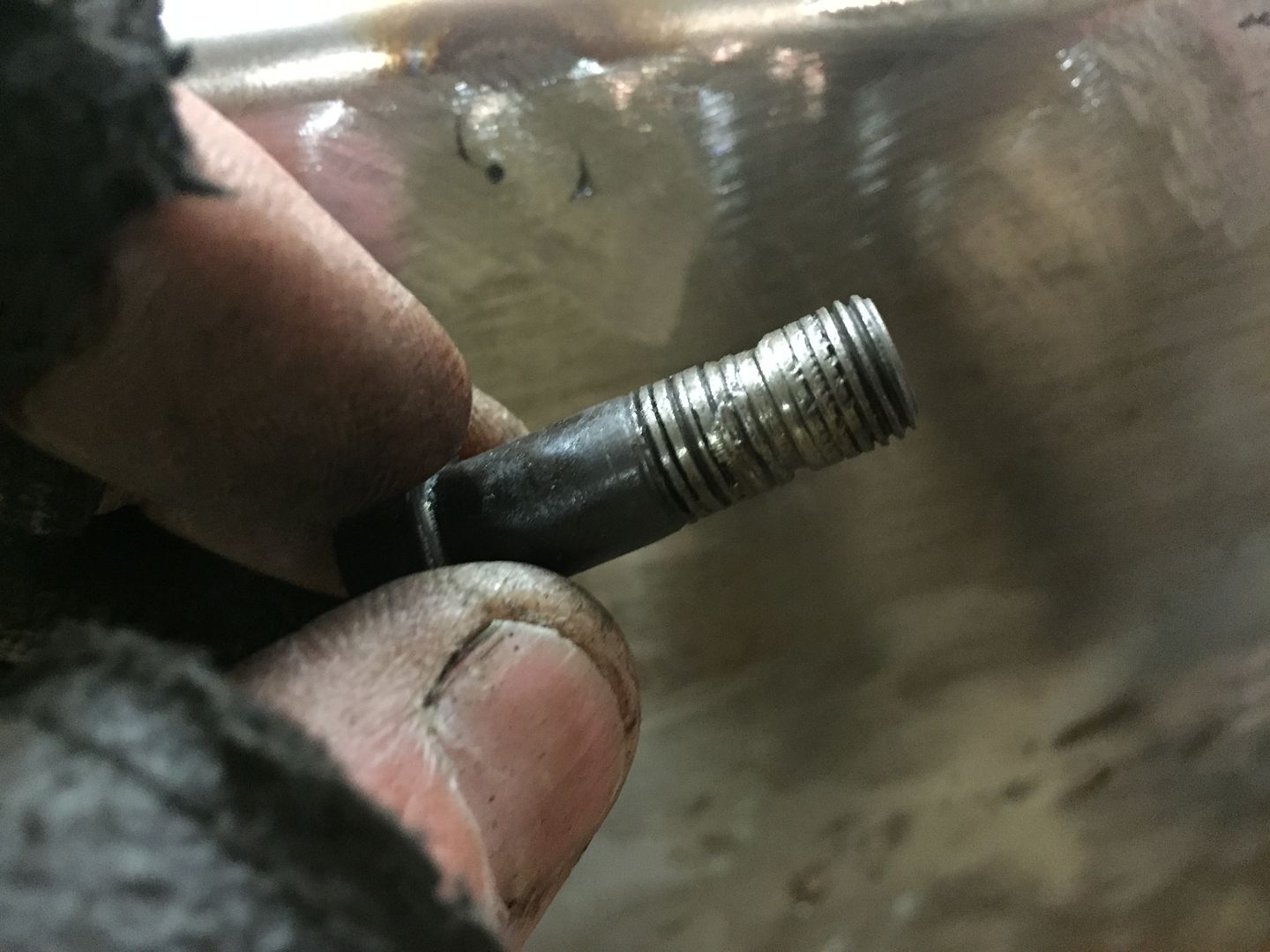 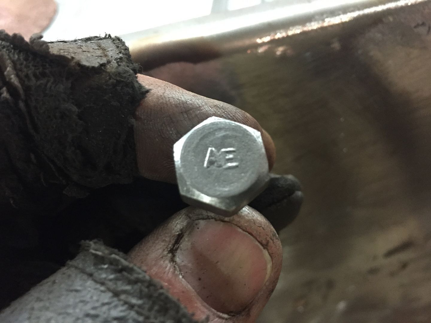 I find the original markings on the bolts to be fascinating. What is more fascinating is when you try to find a replacement for a damaged one, and compare the quality to modern day bolts. |
|
|
|
Post by Haines Garage on Dec 12, 2014 0:54:46 GMT -5
Before attempting to install the new piston, do the following. Remove the pin keeper bolt and lock washer. 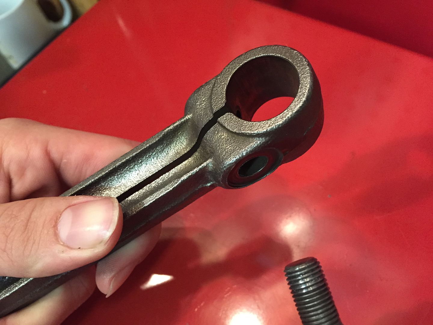 Then insert the pin, check for a smooth fit. You should be able to rotate it by hand with some resistance. not tight. If you cannot insert the pin, pry gently with a large screwdriver the slots below the radius . DO NOT DAMAGE THE PIN AREA ON THE CONNECTING ROD. 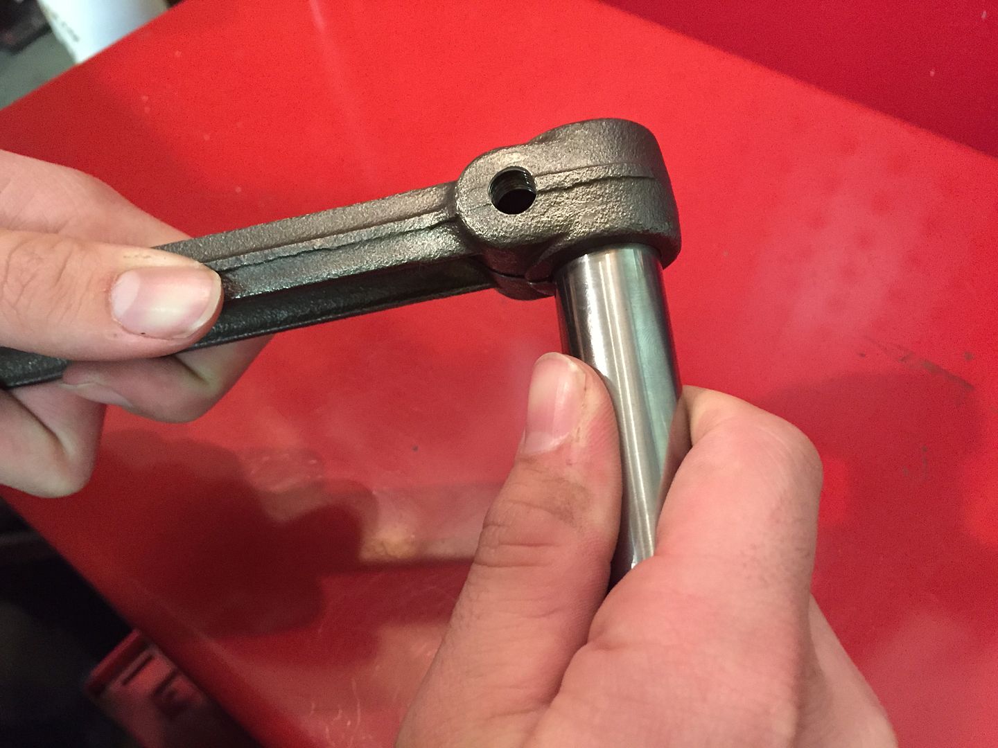 You are now ready to install the Piston. PISTON IS INSTALLED T-SLOT OPPOSITE SIDE AS OIL SQUIT HOLE The pin should be able to be pressed in by you thumbs  Line up the bolt slot in the pin, square as pictured. 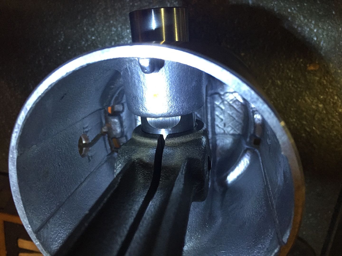 |
|
|
|
Post by Haines Garage on Dec 12, 2014 1:16:42 GMT -5
You can check though the bolt hole to align the slot. Then install the bolt and lock washer. Install the piston assembly into a vice, as close to the piston as you can, with out scratching it, and giving you the most room for a wrench. 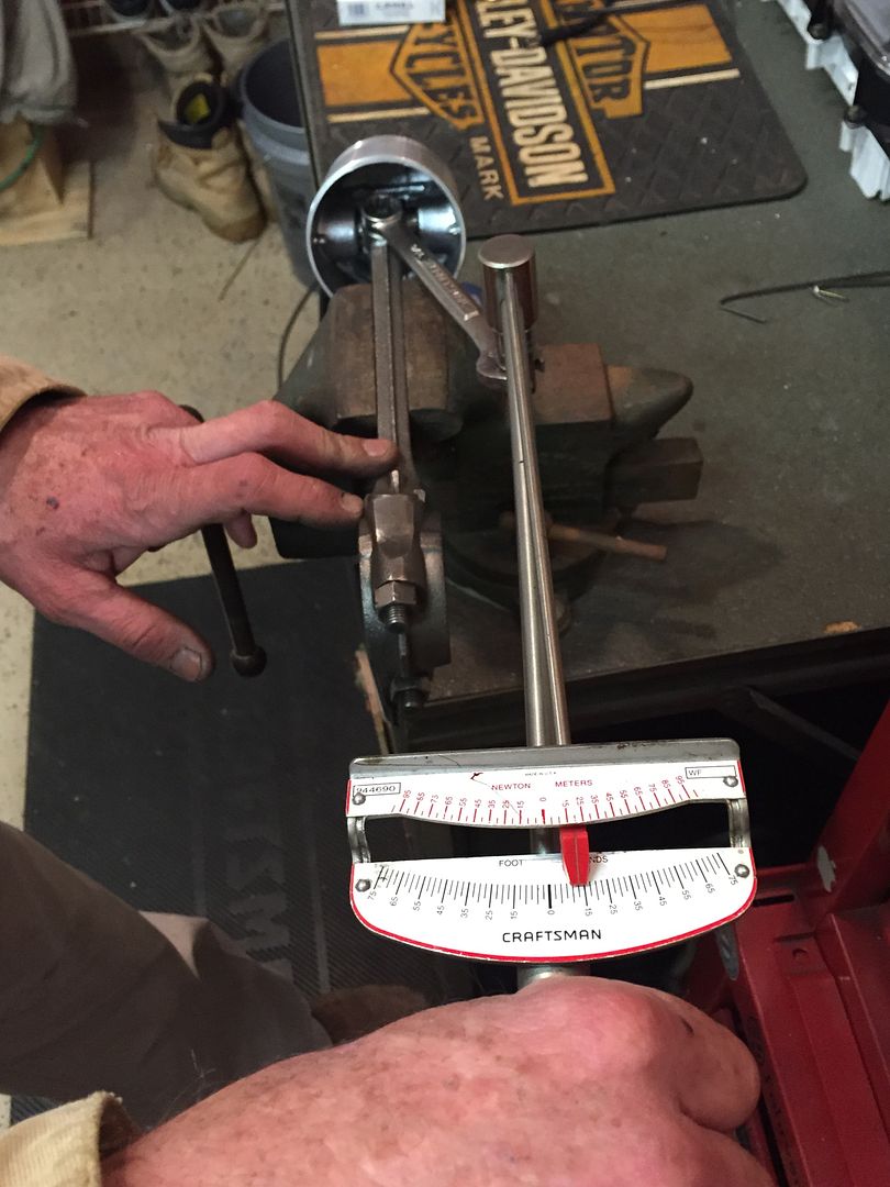 I use a make shift rig to torque the bolts to 35 ft pounds. A 9/16 wrench, a 3/8 to 1/2 in adapter and a 3/8 torque wrench. Hey...It worked!  |
|
|
|
Post by Haines Garage on Dec 12, 2014 1:26:33 GMT -5
Repeat the process for all Four Piston Assemblies. When done, I laid them out in order, 1234. 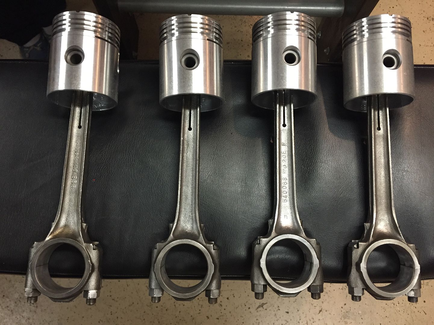 Notice the markings on the Connecting Rods. This goes back to the comments in the previous posts. On my connecting rods the markings are opposite of their correct order. 1 and three the same, 2 and 4 the same. Here are the photos of the bearing keepers. 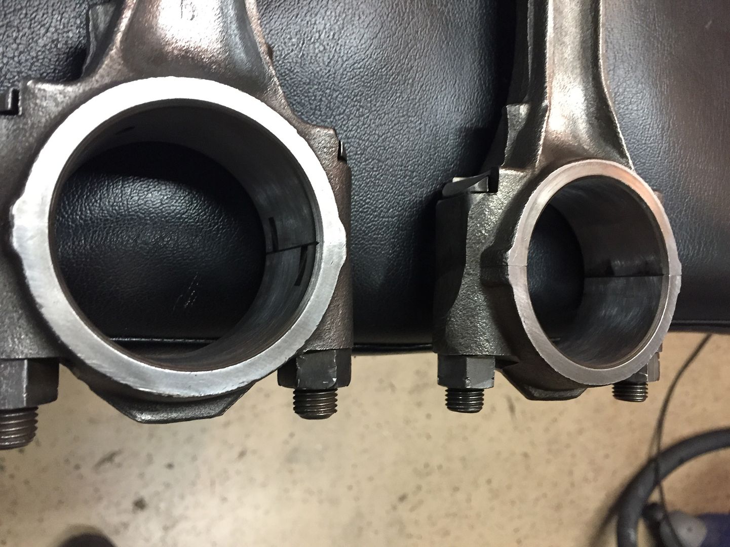 |
|
|
|
Post by Haines Garage on Dec 12, 2014 1:27:25 GMT -5
Piston assemblies are ready to be ringed, and installed on the crankshaft.
|
|
|
|
Post by Haines Garage on Dec 13, 2014 9:24:40 GMT -5
Before I install the crankshaft, I will install the engine mounting plate. If you do this correctly, it will take a little time. Original studs removed, and cleaned thoroughly. 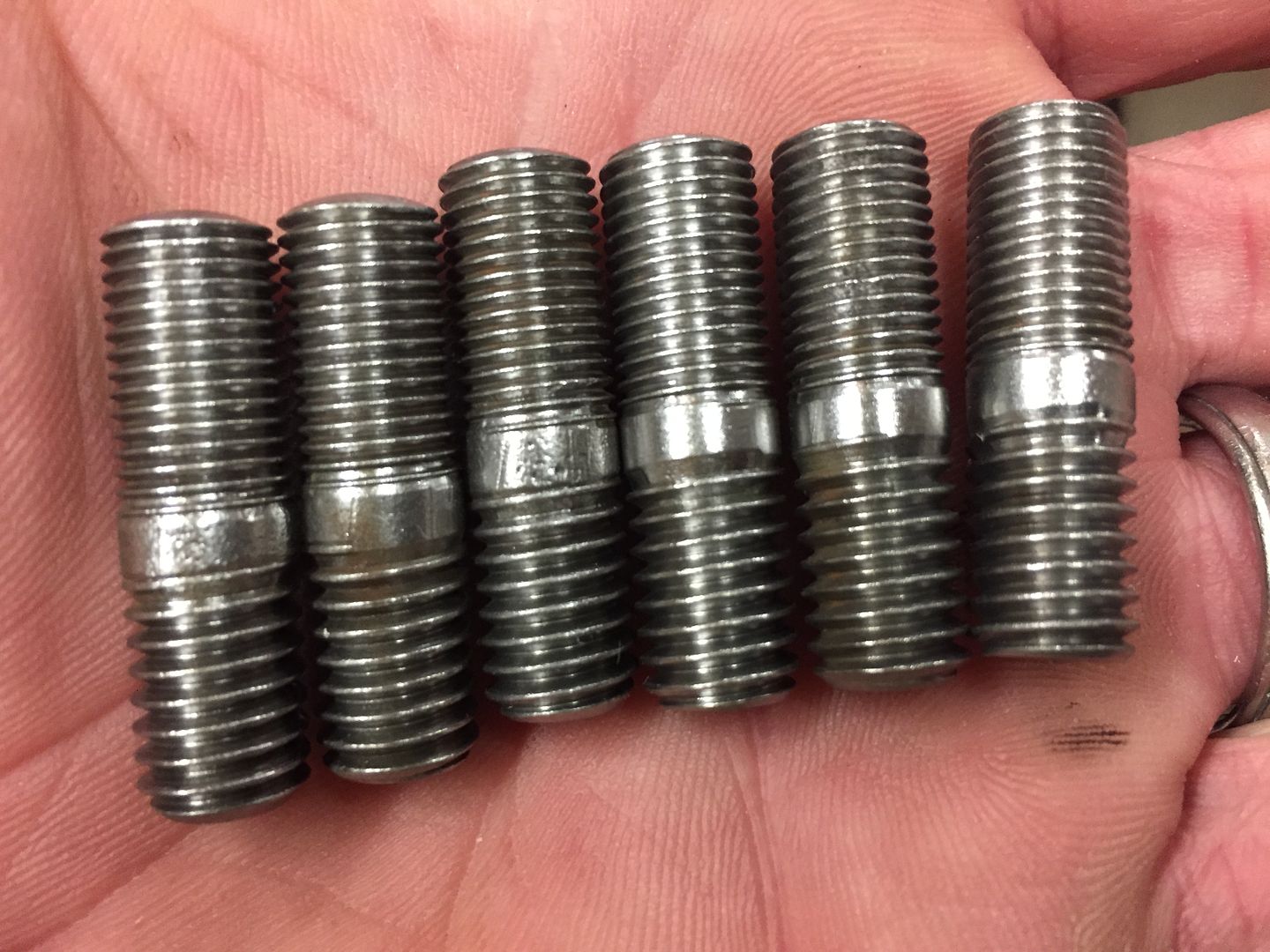 Mounting face on block cleaned with lacquer thinner and clean rags. 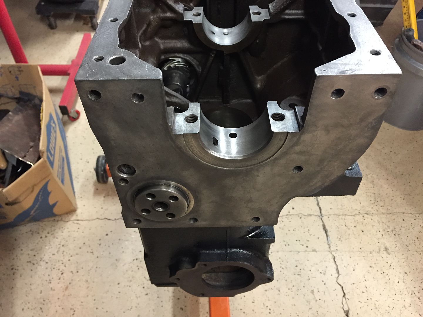 It is important to seal the studs. Many of them penetrate into the inside of the block. 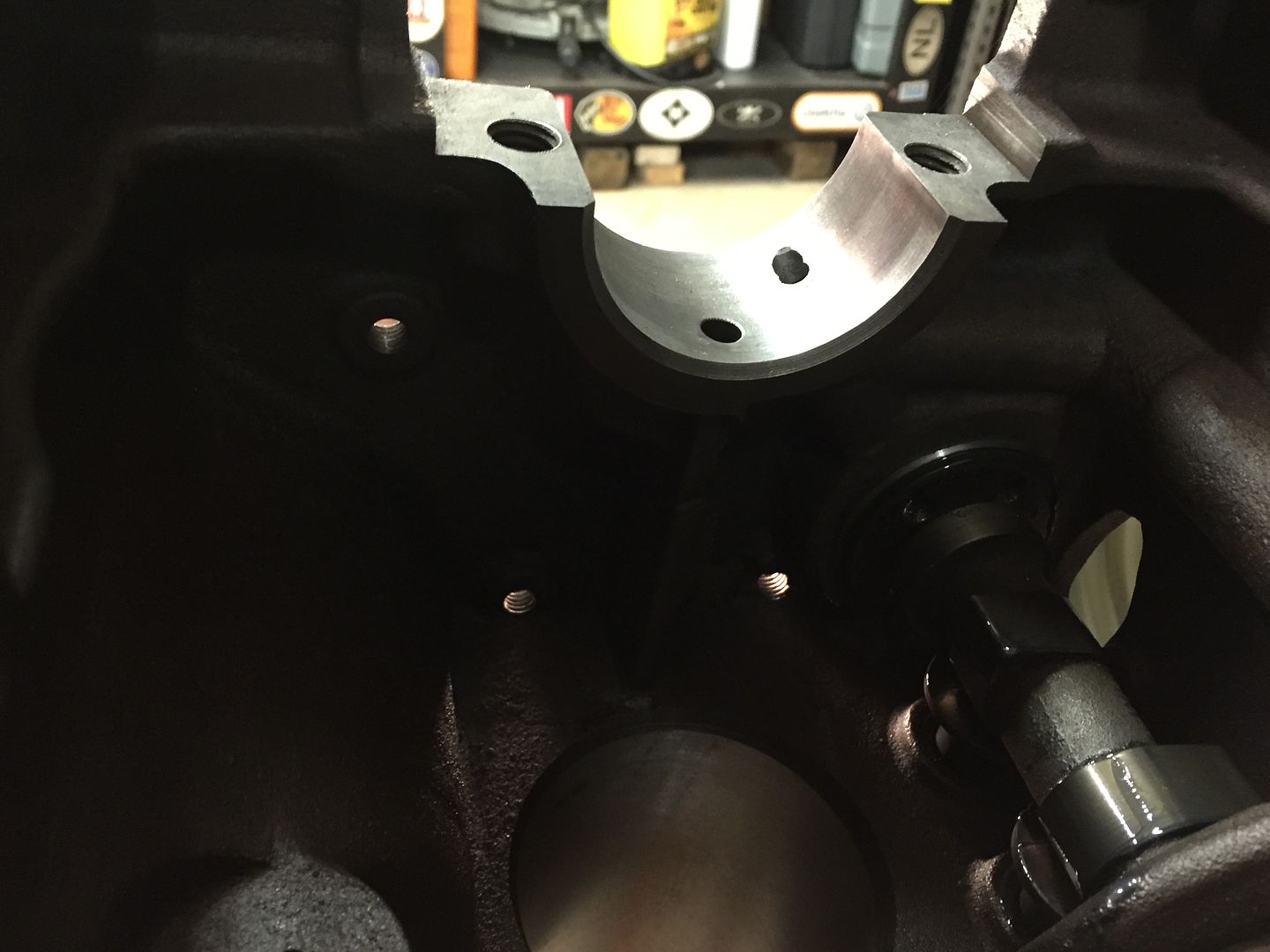 |
|
|
|
Post by Haines Garage on Dec 13, 2014 9:39:54 GMT -5
When I install the studs back into the block, I coat the course threaded ends with Permetex #2. Course threads fit into the block. The treads in the block have had a tap run through them, and are clean. 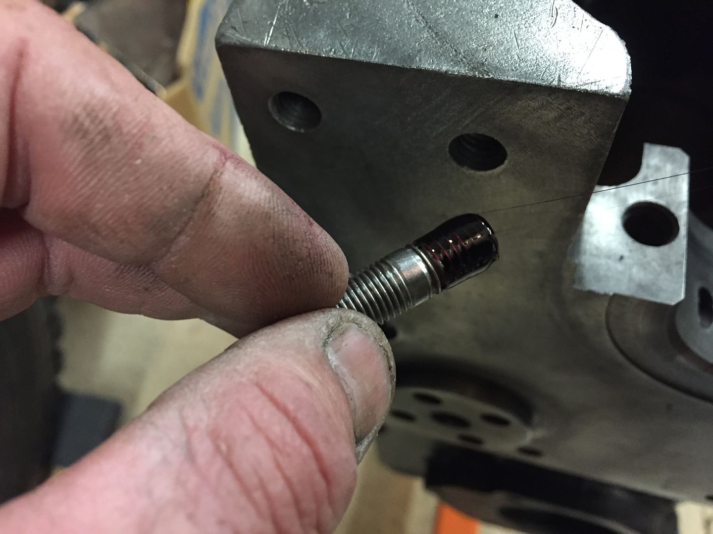 I used the double nut method to install the studs. Take to nuts, and thread them onto the stud. Tighten them with two wrenches against each other, so that you may use the outside nut to tighten the stud in the block. 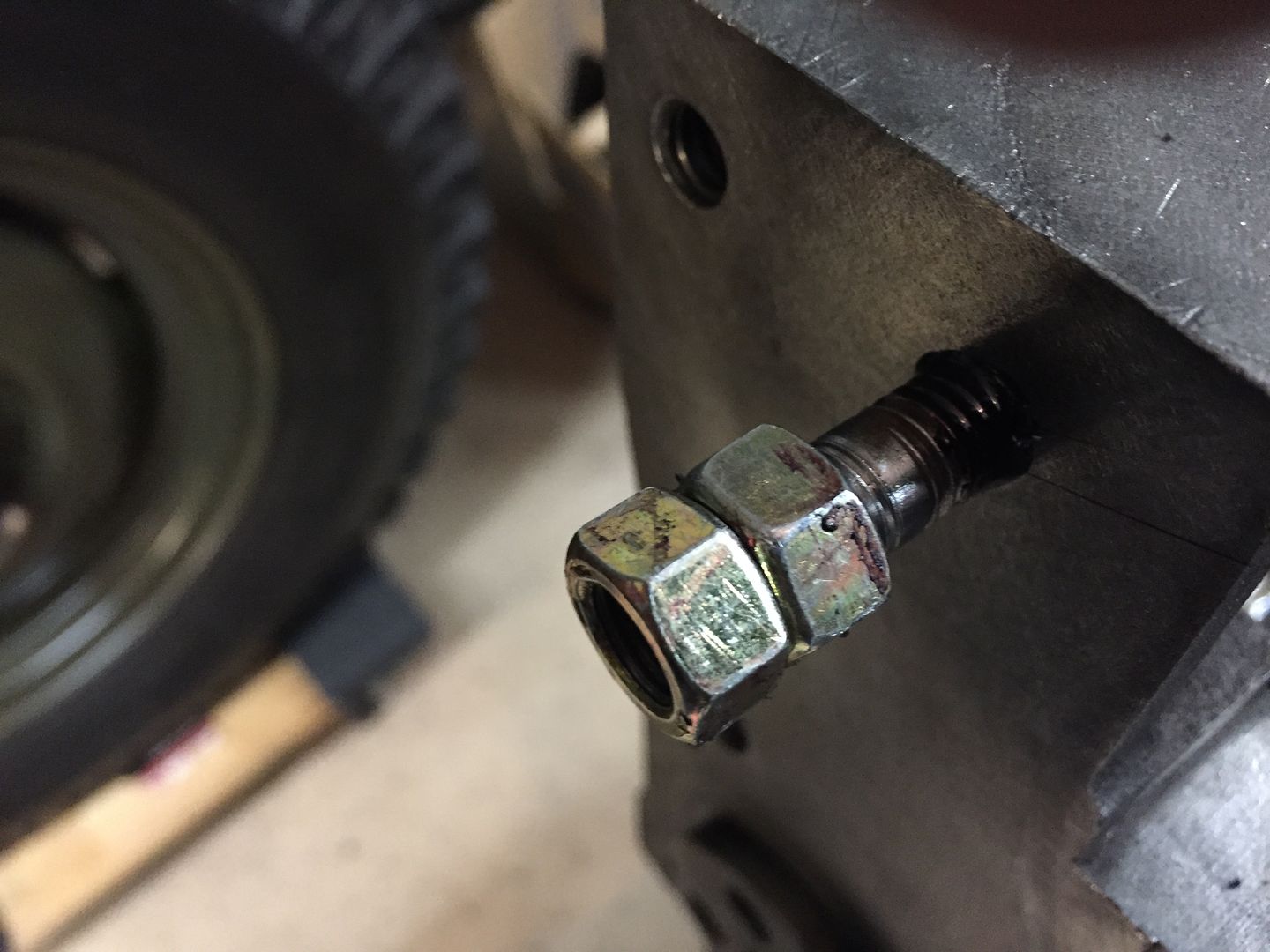 I tighten the stud until it bottoms out, or stops entering the block. Then simply unloosen your nuts with two wrenches. 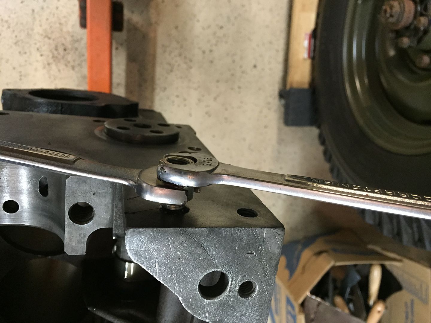 The nuts spin off the stud 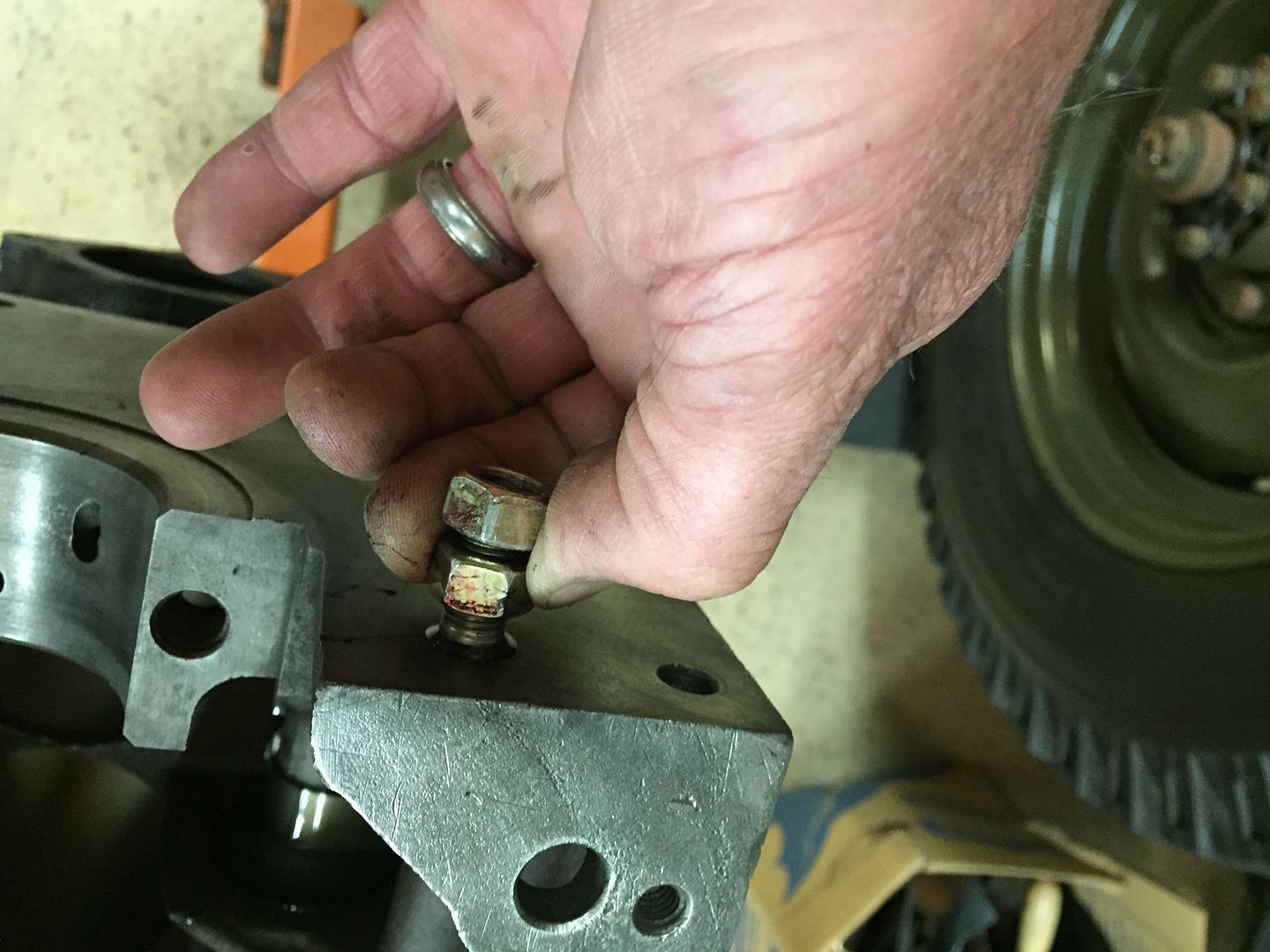 Then I clean any excess sealant off the stud and block face. 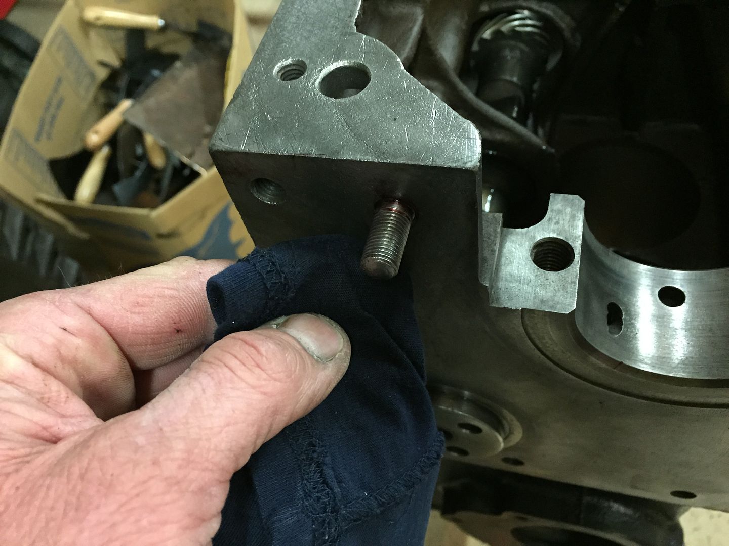 There are 6 studs on the block, and three bolts that hold the mounting plate in place. The bolts surround the area that the camshaft protrudes out of the block. |
|
|
|
Post by Haines Garage on Dec 13, 2014 10:11:37 GMT -5
From the gasket kit, this is the proper gasket for the chain drive engine. Round hole for the camshaft. Kits usually come with both early and later style gaskets. 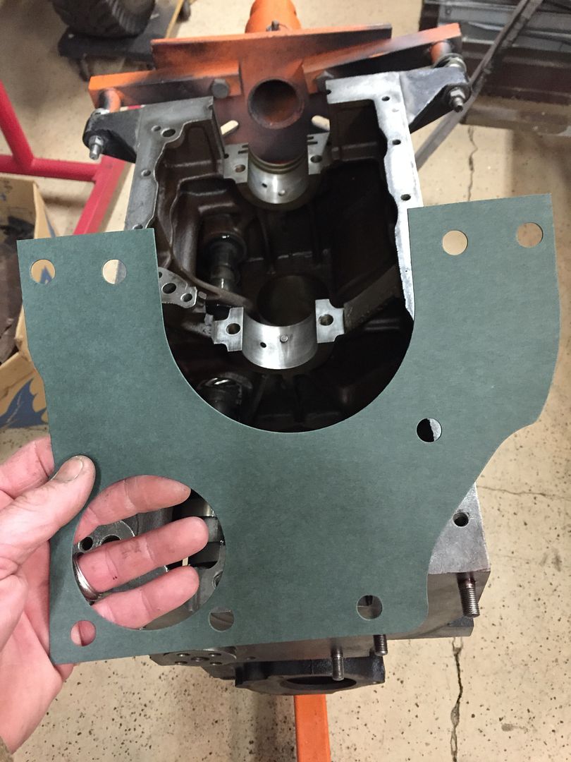 I coat the mounting face on the block with Permetex #2 and a small brush. A light even coat. 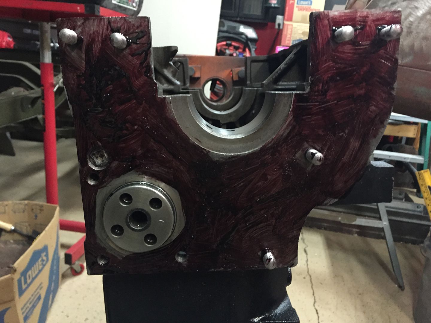 I lay out some brown paper, and coat the corresponding side of the gasket. 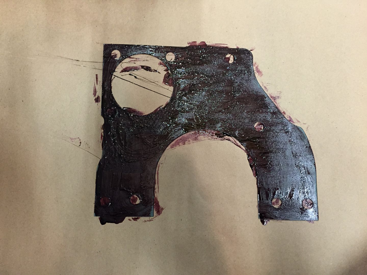 Then install the gasket onto the face of the block, press it into place gently with your fingers. 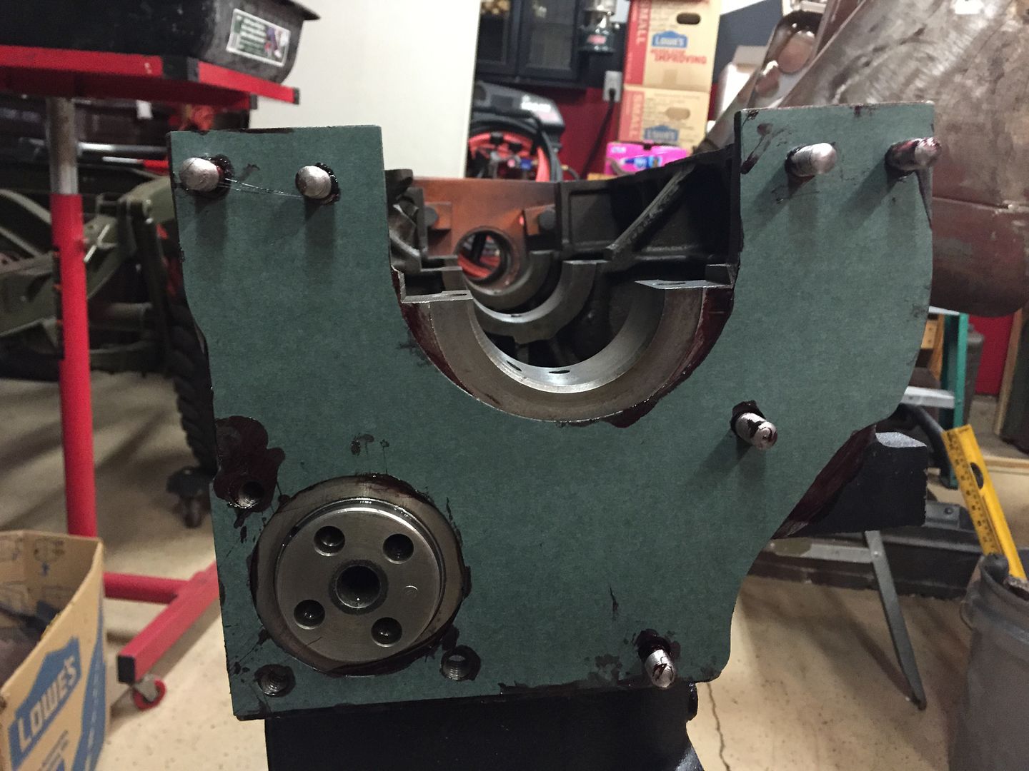 Once installed, coat the face of the gasket with Permetex #2 Then coat the Clean mounting bracket with sealant as well. Install the bracket, install the lock washers and nuts to the studs, and install the three bolts . I tighten these snug with a wrench, then torque all bolts and nuts to 35 Ft Pounds. 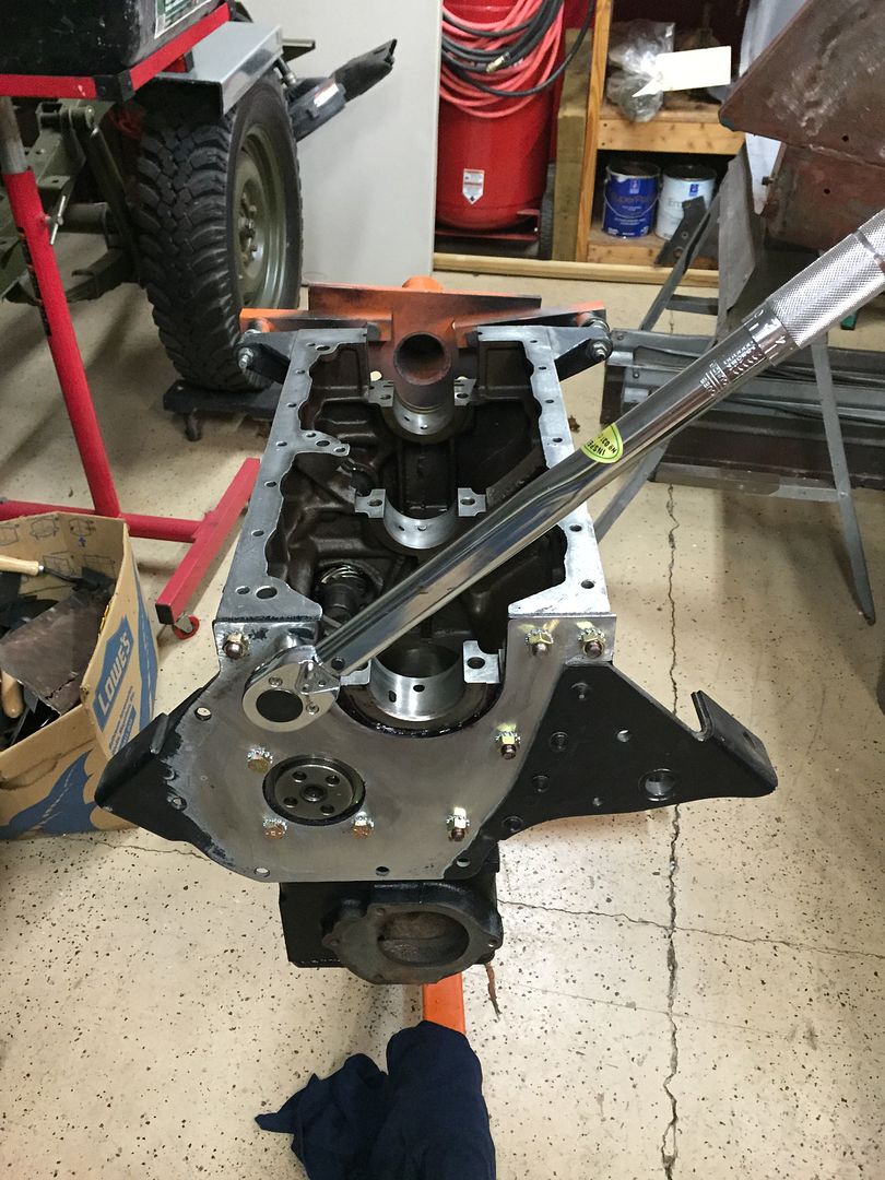 Clean up any excess sealant around the crankshaft area, camshaft , and block. Mounting Bracket is installed. |
|
|
|
Post by Haines Garage on Dec 14, 2014 14:31:09 GMT -5
I am ready to install the Crankshaft. Even though I had the crank ground, and am installing. I still want to check the clearance between the crank and the bearings. I will do this using a Plastigauge. Before installing the new bearings, I clean one last time with lacquer thinner, the bearing surfaces on the block, and the caps. Notice the location of the dowels. There are no dowels on the front bearing, as the shoulder on the front bearing holds it in place. 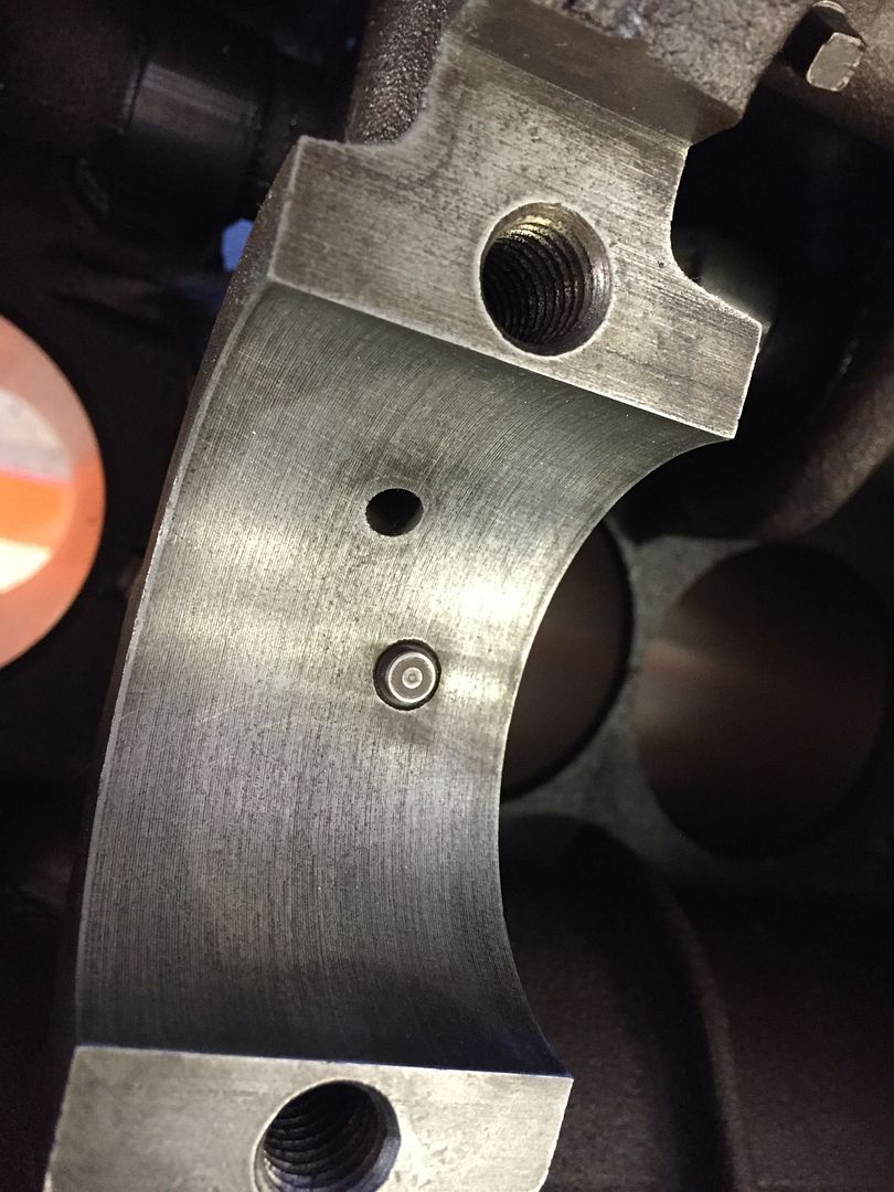 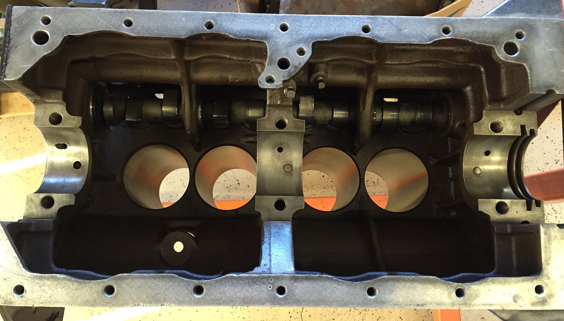 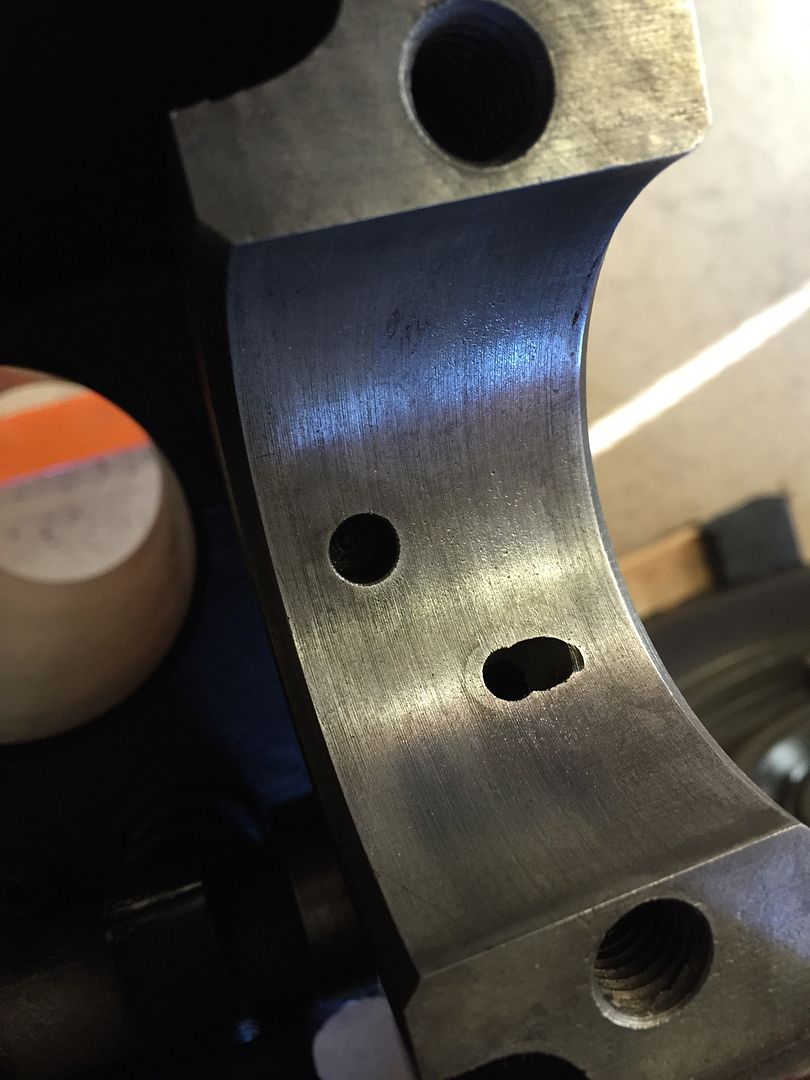 This is a picture of the new main bearings, they are marked upper and lower. 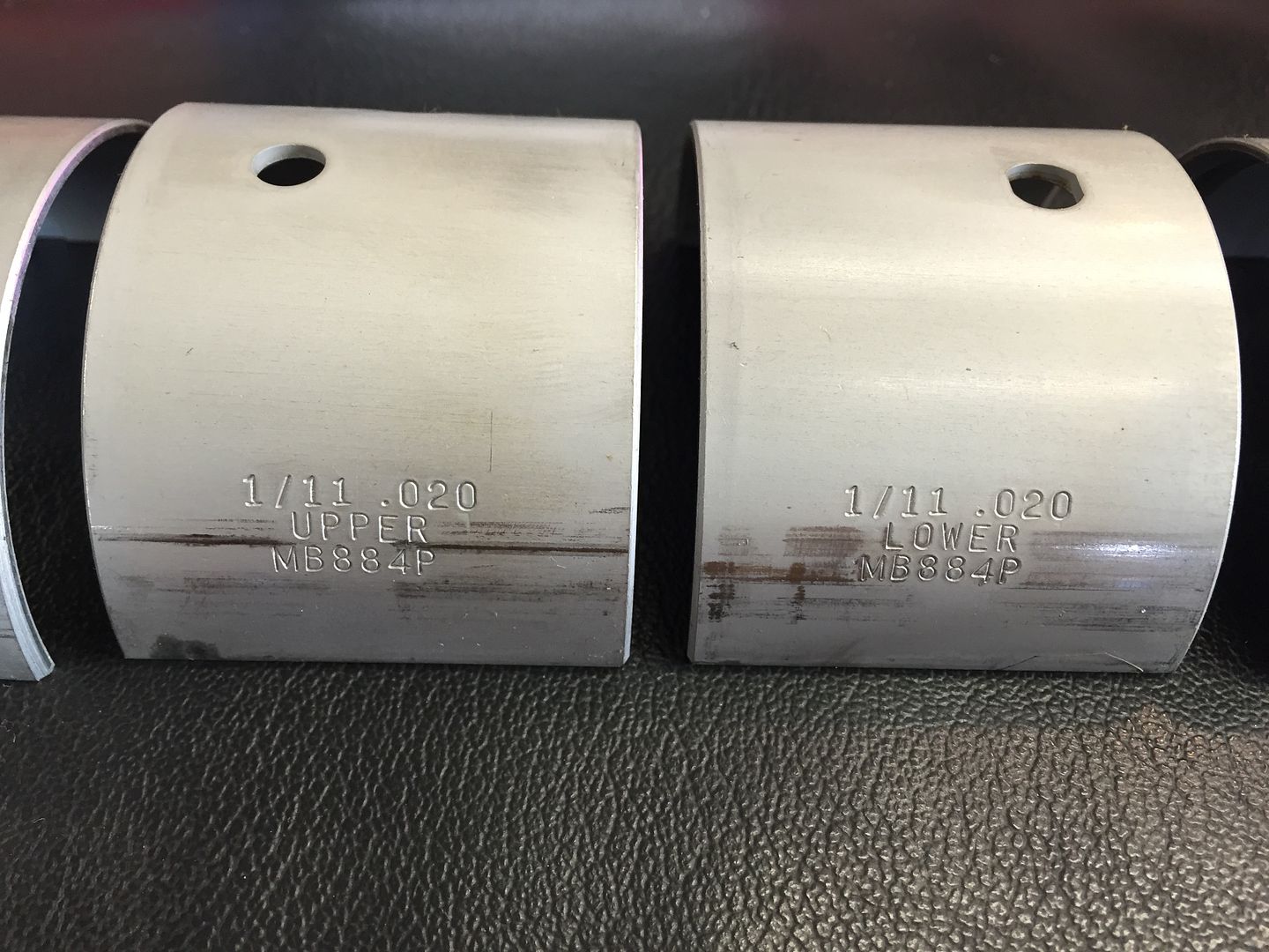 A comparison shot of an old, and new bearing. 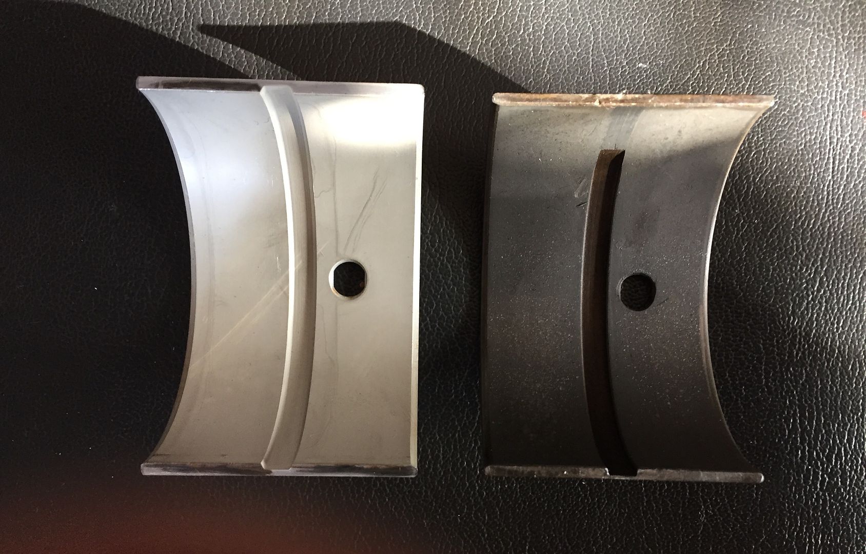 |
|
|
|
Post by Haines Garage on Dec 14, 2014 15:01:04 GMT -5
Install the upper bearings first. Note the location of the dowel pins, and the oil holes. The bearing only go in one way. I press them in with my thumbs making sure the bearing seats. 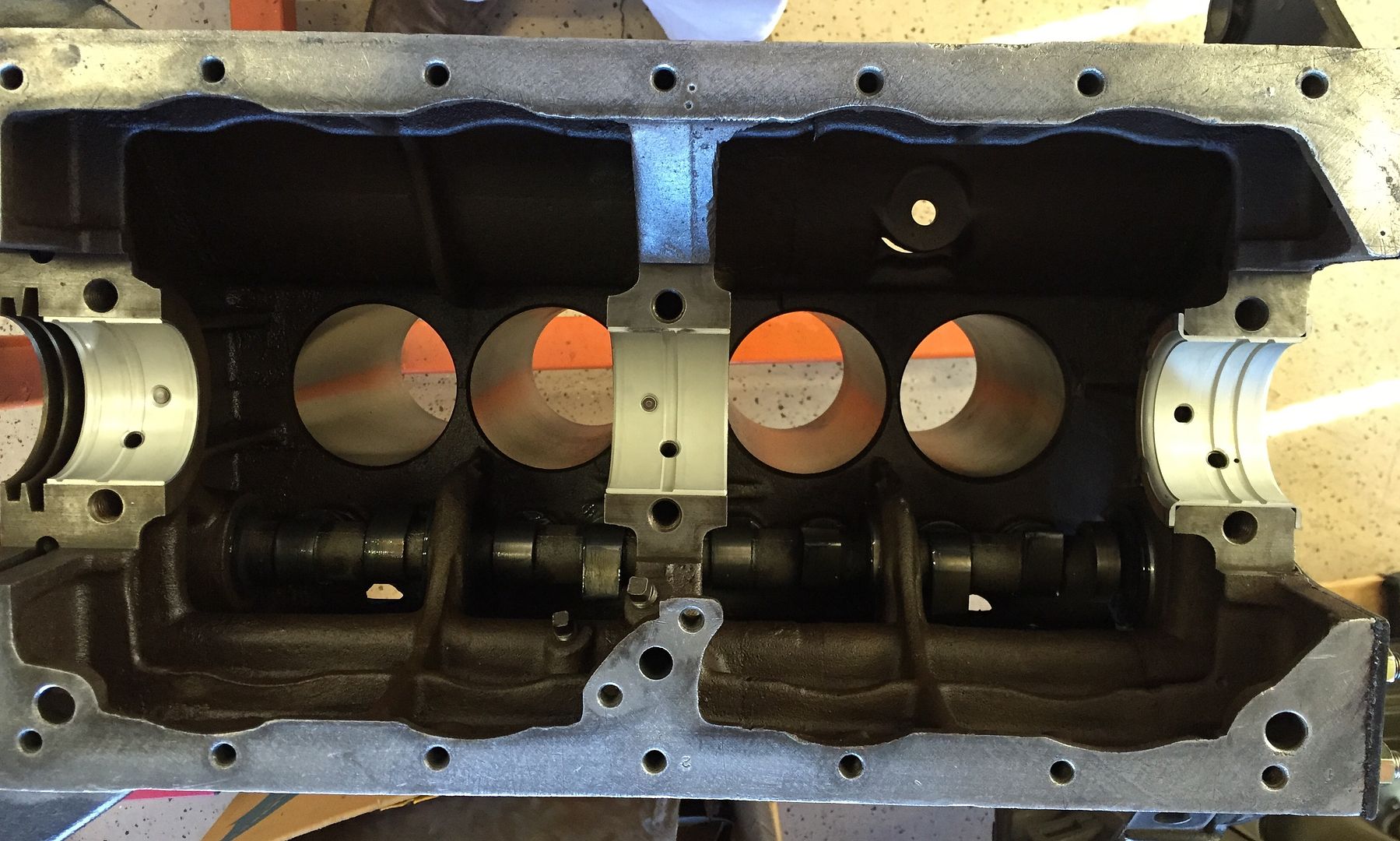 I then install the lower bearings on the caps. 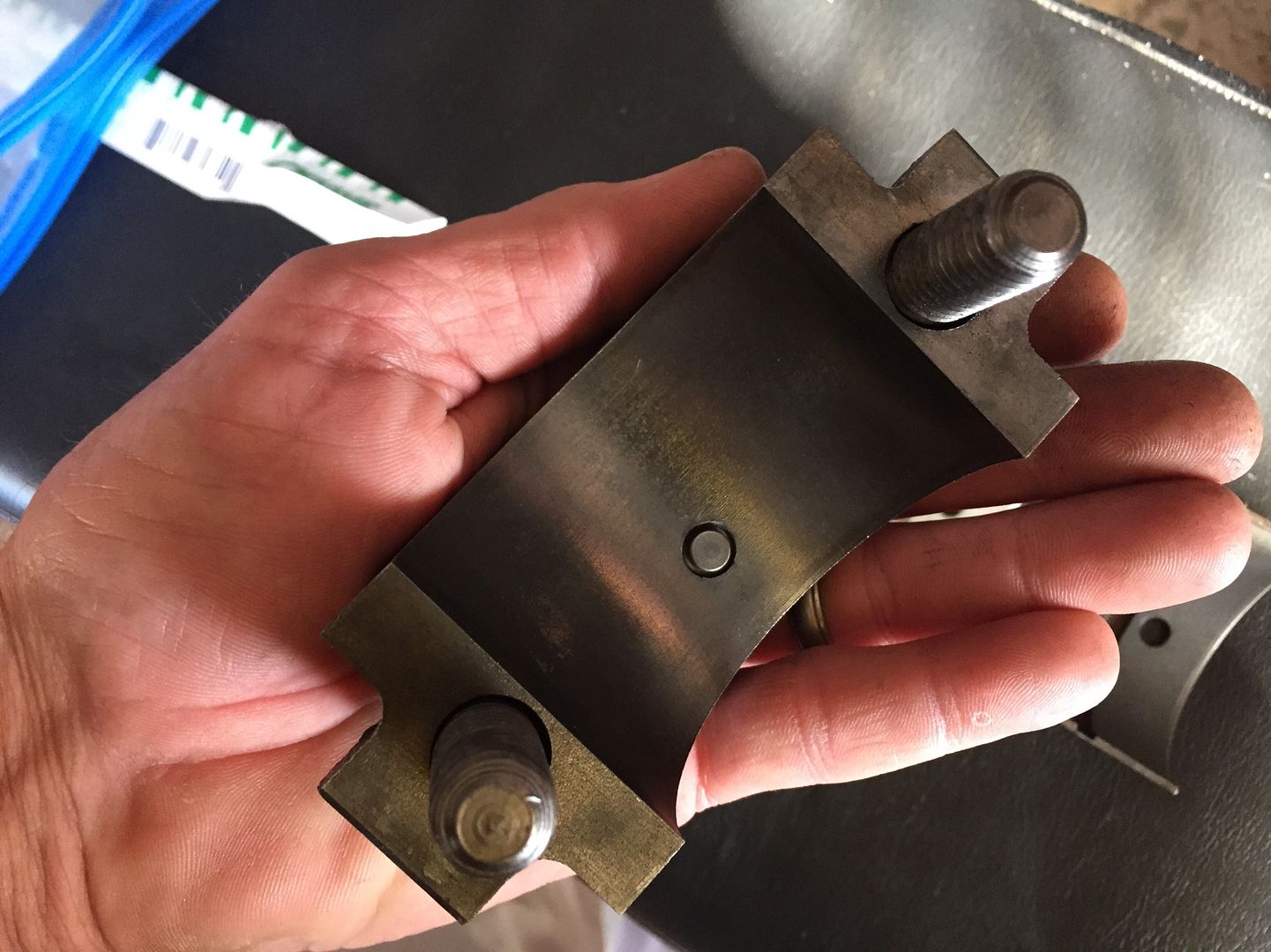 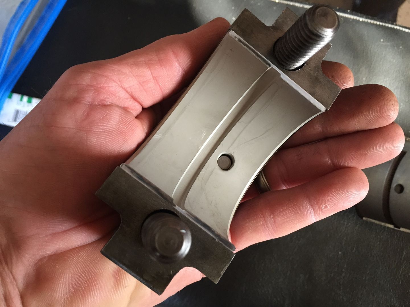 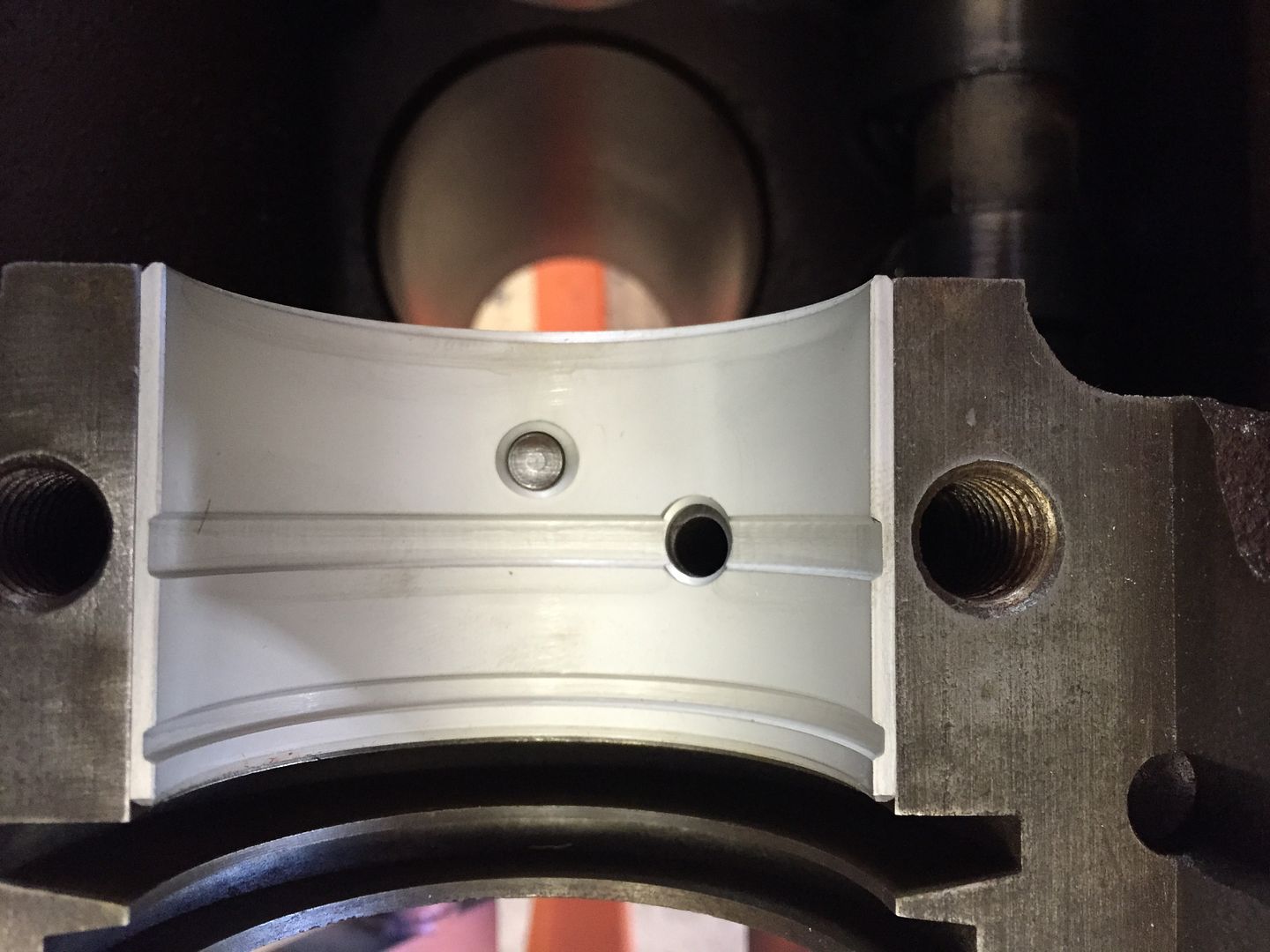 Gently install the crankshaft. At this point I have not installed the rear main seal. |
|
|
|
Post by Haines Garage on Dec 14, 2014 15:40:06 GMT -5
This is Plastigauge. 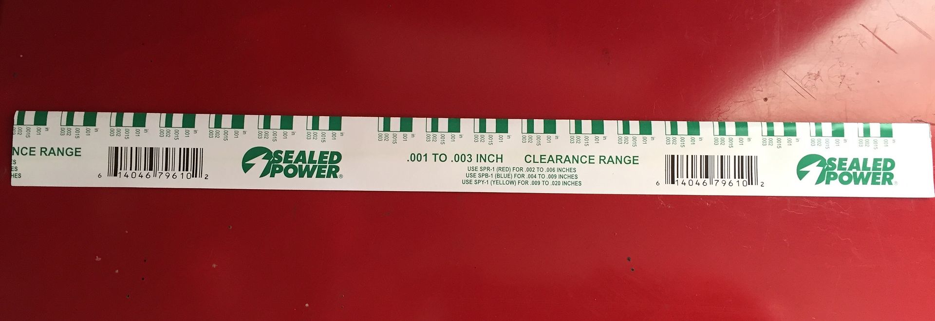 I am using the Green. It measures between .001 to .003 of an inch. For reference the Red measures .002 to .006 of an inch. As per WO Manual Specs, the clearance should be between .003 and .0025. I cut three sections of Plastigauge approximately 1/4 of in inch shorter than the length of my crankshaft journals. Lay the plastigauge length wise on each journal. 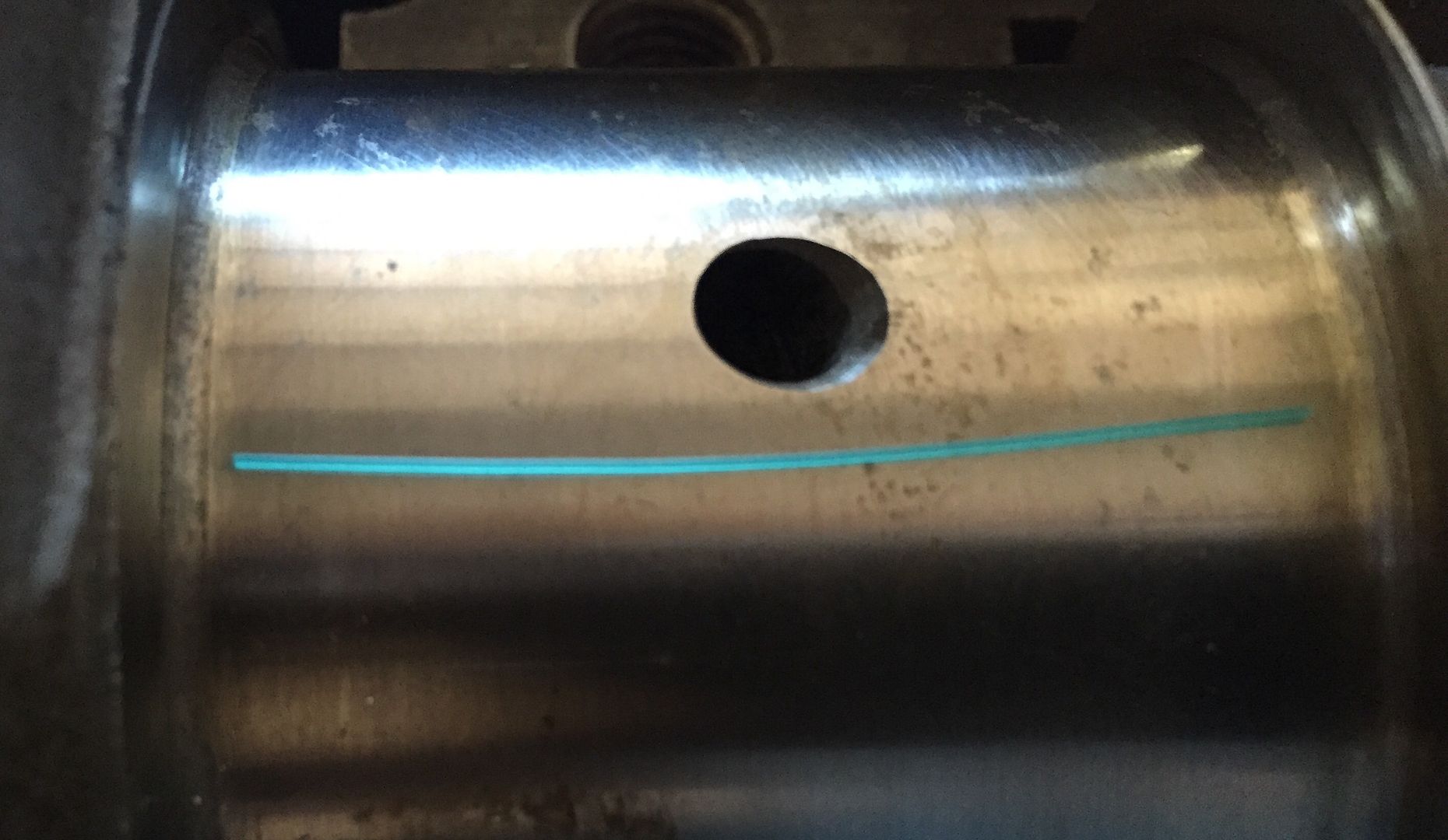 Place your caps in there proper places. I hand tighten each cap bolt, then alternate back and forth to pull the cap on evenly. I only turn each bolt 1/4 of a turn, and torque the bolts to 40 ft pounds. When you finish torqueing all the bolts, remove them! NOT WITH YOUR TOURQUE WRENCH!!  Then use the gauge on the packaging to compare to the compressed plastigauge. 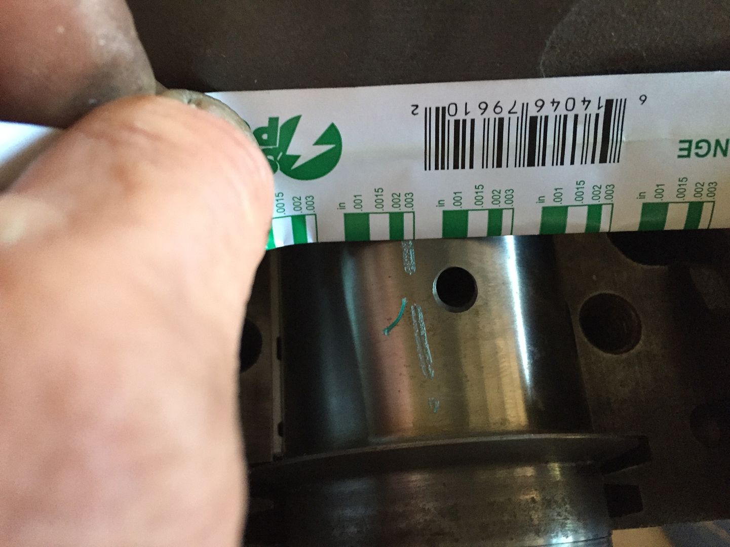 I check each journal the same way. They all read @ .003. You are also looking for any irregularity in the gauge. It should be a uniform flattened shape. Every thing checks out....Time to install the crankshaft for keeps. |
|
|
|
Post by Haines Garage on Dec 17, 2014 17:02:07 GMT -5
Installing The Crankshaft All main bearings are installed. I now move to the installation of the Rear Main Seal. I used Fel Pro Part # BS 3165. It is the rope style seal. The outer rubber gaskets are a smaller diameter than the new modern replacements on this engine. To install, I make sure the seating surfaces are 100% clean. Use a Brass brush, and lacquer thinner. Clean is very important here. Here are the instructions included in my rear main gasket set. 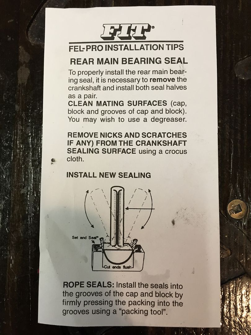 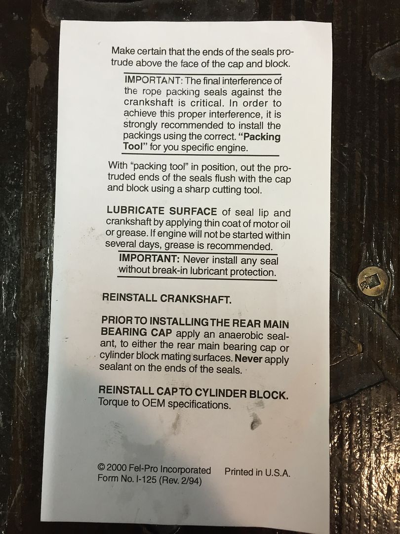 Notice the installation tool shown. I made my own out of a old bearing, and a yard shovel handle. I plug welded the hole in the bearing, and ground it out. This should work well. 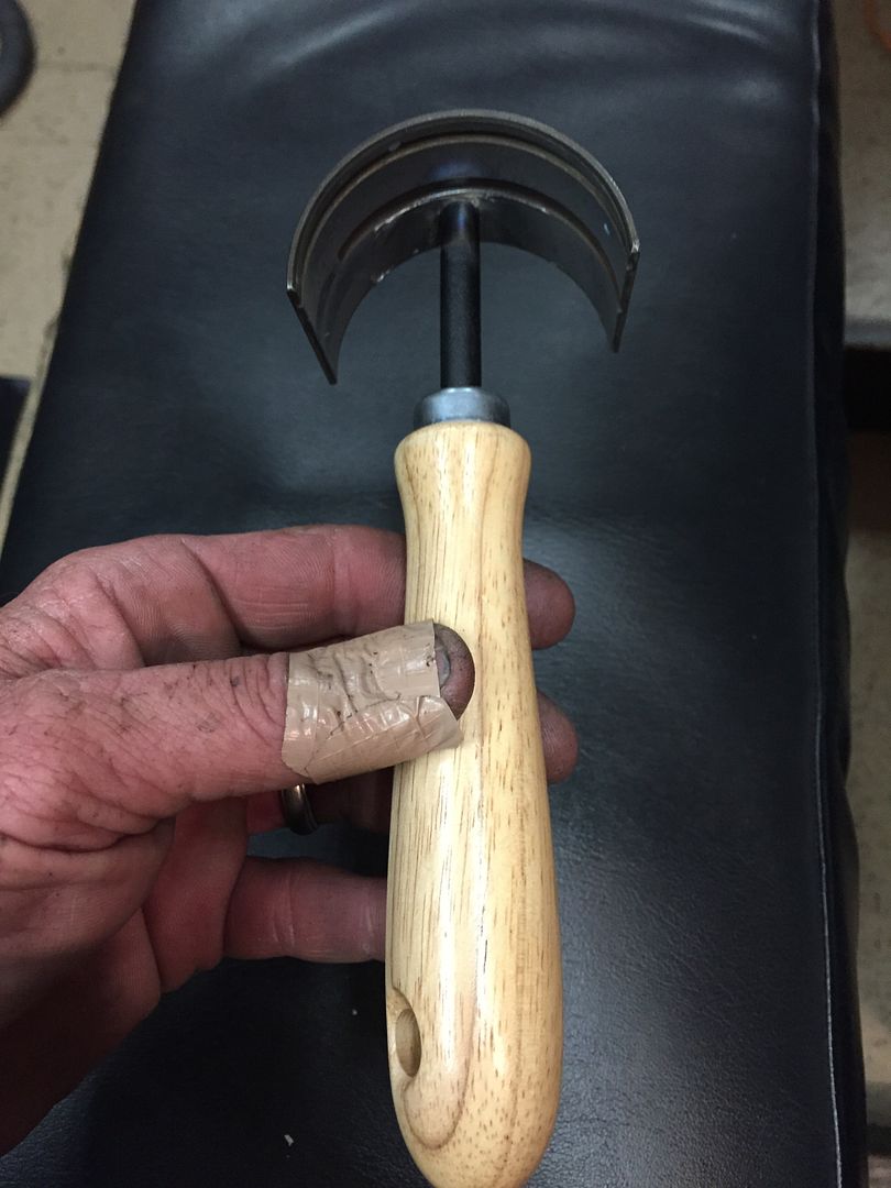 |
|