|
|
Post by Haines Garage on Mar 7, 2014 23:06:45 GMT -5
Stainless??? All the salt rain here in SC   (That's a fight from long ago  ) When we get to the end of the thread here, we will do some "adjusting"  Cool project, I am glad you two turkeys brought it up...  |
|
Deleted
Deleted Member
Posts: 0
|
Post by Deleted on Mar 7, 2014 23:11:01 GMT -5
That's right,,,,,,,,, I completely forgot the salt rain  Lee  |
|
Deleted
Deleted Member
Posts: 0
|
Post by Deleted on Mar 8, 2014 7:48:10 GMT -5
My take on stainless is that it galls in the threads and strips easy. Make sure you antiseize things. John
|
|
|
|
Post by Haines Garage on Mar 8, 2014 12:28:22 GMT -5
My take on stainless is that it galls in the threads and strips easy. Make sure you antiseize things. John Not my Stainless...its special. I will and do use anti seize often. Those pedals are not tight yet. Have to remove them when I someday install my tub. |
|
|
|
Post by Haines Garage on Mar 8, 2014 15:17:10 GMT -5
We got off on a little rod tangent there for a minute. Lets go back a little.  to here..... 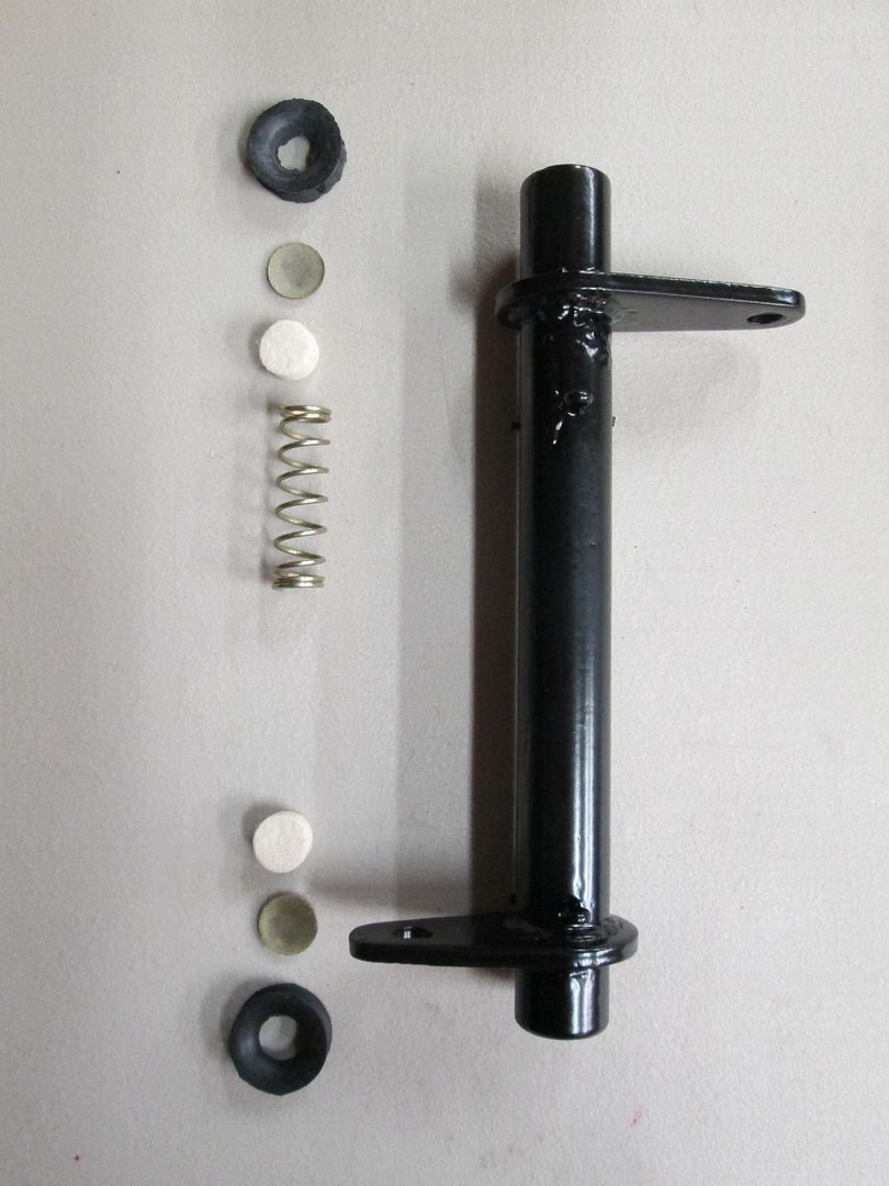 The lever and control tube assembly. If you look closely at the photo, I have already installed the cotter pins and painted the tube. The tube has a long and a short "ear".The side with the long ear, has an inside depth to the cotter pin of 2 1/4 inches. The side with the short ear has a depth to the cotter pin of 1 1/4 inches. The photo shows the proper order for the inner workings to be installed. |
|
|
|
Post by Haines Garage on Mar 10, 2014 14:45:15 GMT -5
One ball stud is threaded into the transfer case housing (D-18), and one ball stud bolts onto a bracket that mounts to the frame.(picture later installed) Transfer Case Ball Stud 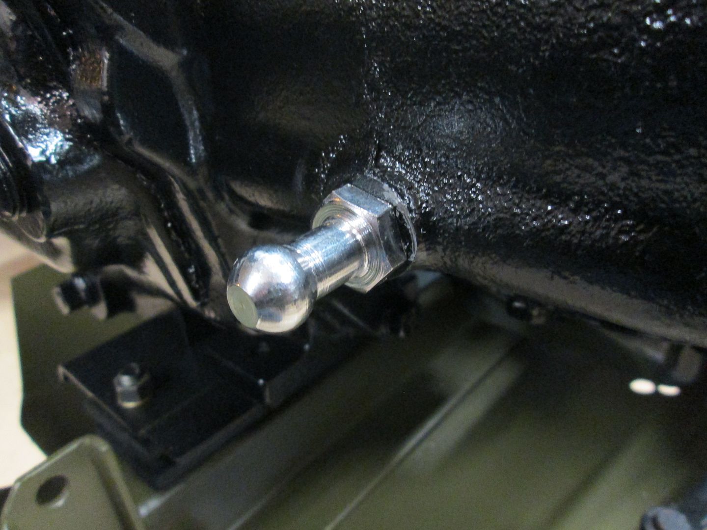 I gave each end of the control tube a couple of shots with the grease gun, high temp grease. 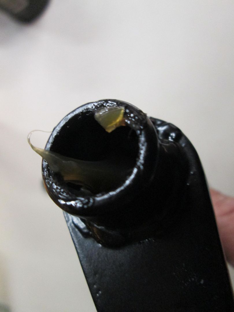 As pictured, insert the spring, felt spacer, and metal spacer into the tube. (The cotter pins stop the parts) The metal spacer or cup, is inserted so that the ball studs seat in them. In other words, radius side out. 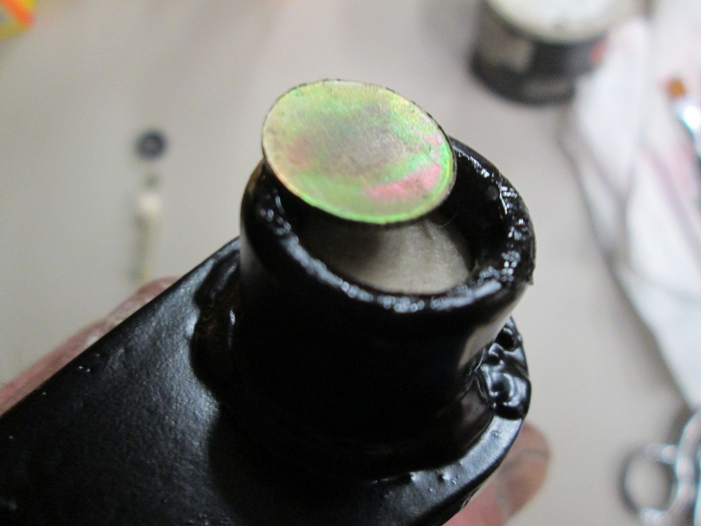 I then lubed each ball stud with a dab of high temp grease, and install the rubber dust boot. 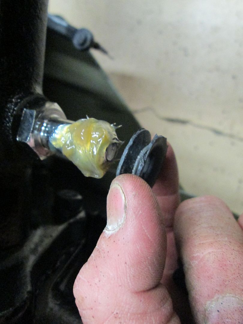 The Long ear side of the control arm is inserted onto the ball stud, transfer case side. Insert the bracket with ball stud onto the control arm, and slip it into place, lining up with the two holes on the frame. 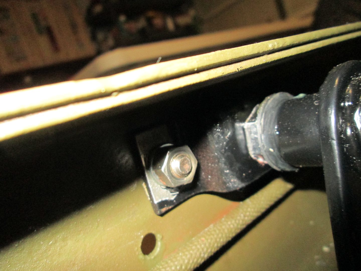 I had a little trouble with my paint poping as I tightened the bolts down. I will prime, and touch up with a brush later, on final detail painting. Bolt holes for bracket side from outside the frame rail. 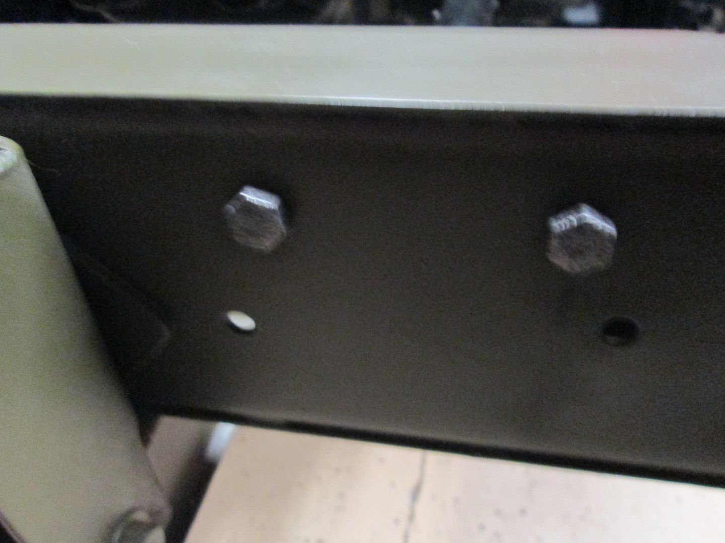 |
|
|
|
Post by Haines Garage on Mar 13, 2014 19:07:41 GMT -5
With the control arm assembly installed, I move to the forward to the pedals. 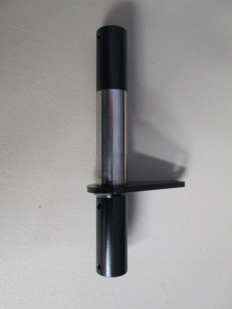 I masked off, and primed and painted the areas on my new idler shaft. I did not paint the area that is greased, and rotates in the frame mount. This paint will get scuffed during assembly, but I figured it couldn't hurt to be there. I used a drill, and an old 12 gauge shot gun brass cleaning bush to remove any paint, or corrosion inside the frame mount for the idler shaft. 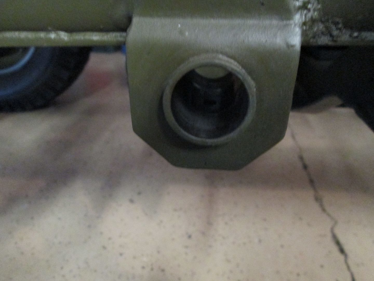 If you look close you will see where a zerk grease fitting comes through the bottom. I cleaned that out as well, and will install a new fitting. |
|
|
|
Post by Haines Garage on Mar 13, 2014 20:20:32 GMT -5
I greased the unpainted surface of the shaft with high temp grease, insert in from the inside of the frame, with the "ear" as pictured. I nstalled the stainless steel cotter pin and first washer( also purchased from Walcks) I apply high temp grease to the area where the brake pedal will ride. 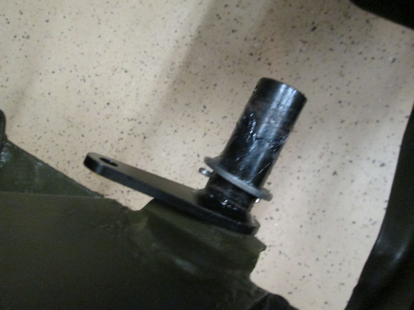 I also apply a thin film of high temp grease to the inside of my brake padal 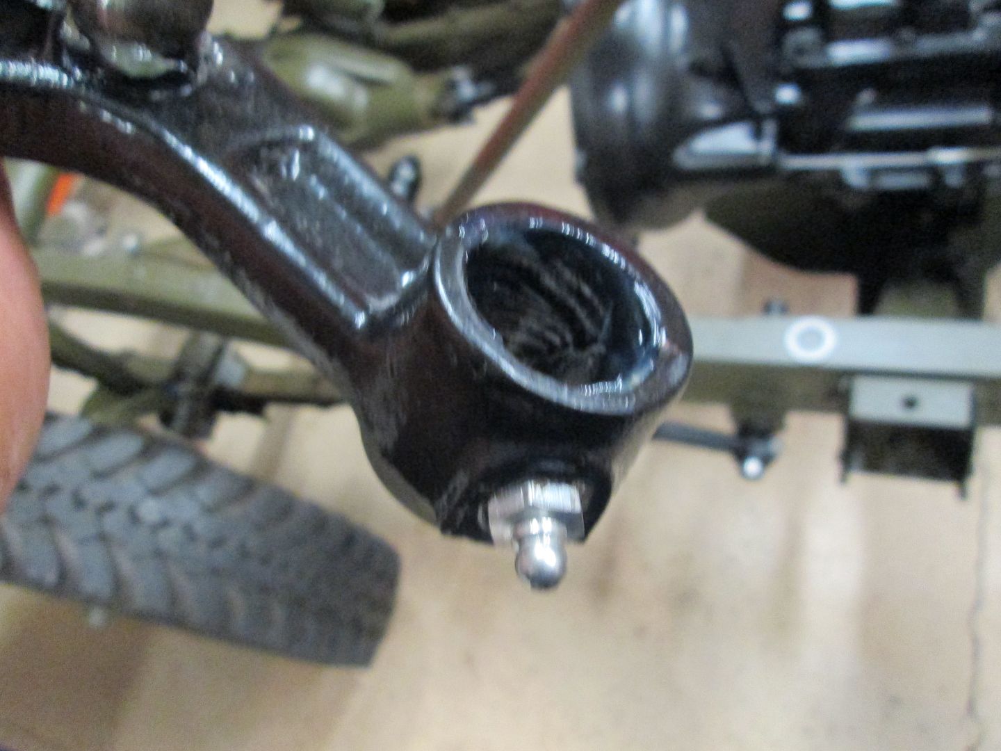 And a small dab to the push rod that is inserted into the master cylinder. 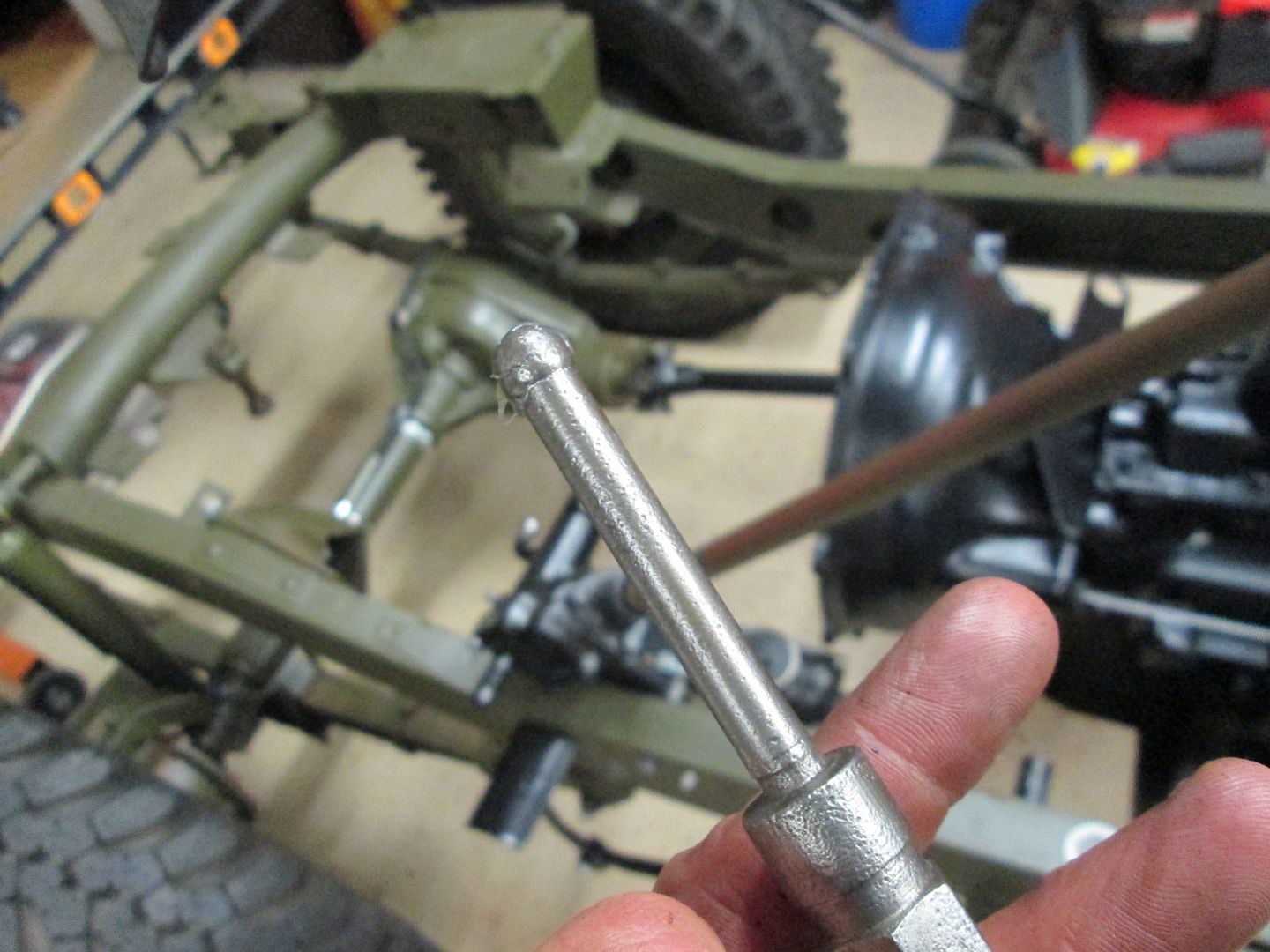 Here are pictures of how the push rod is inserted into the rubber dust seal, notice the lip on which the seal seats 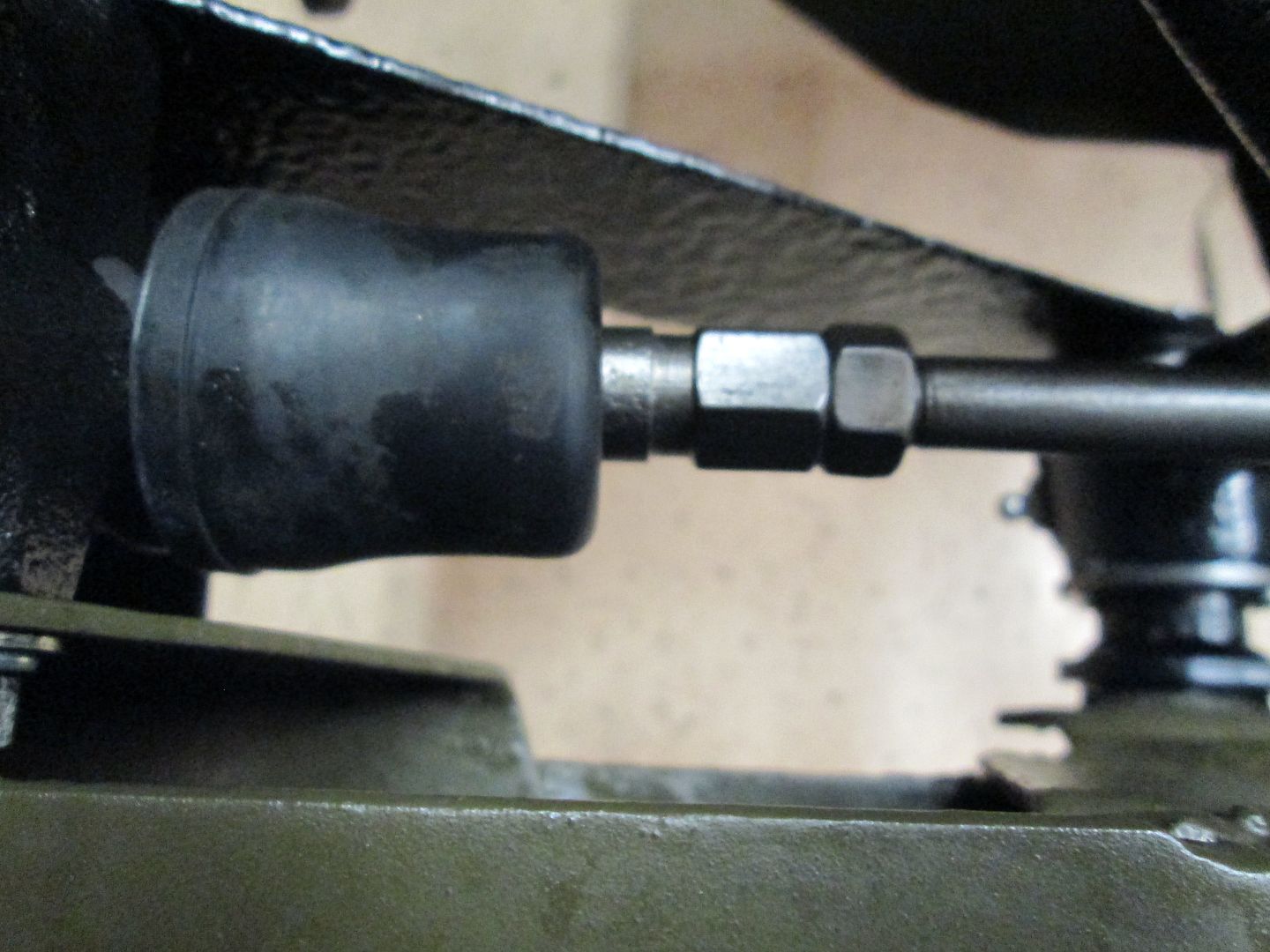 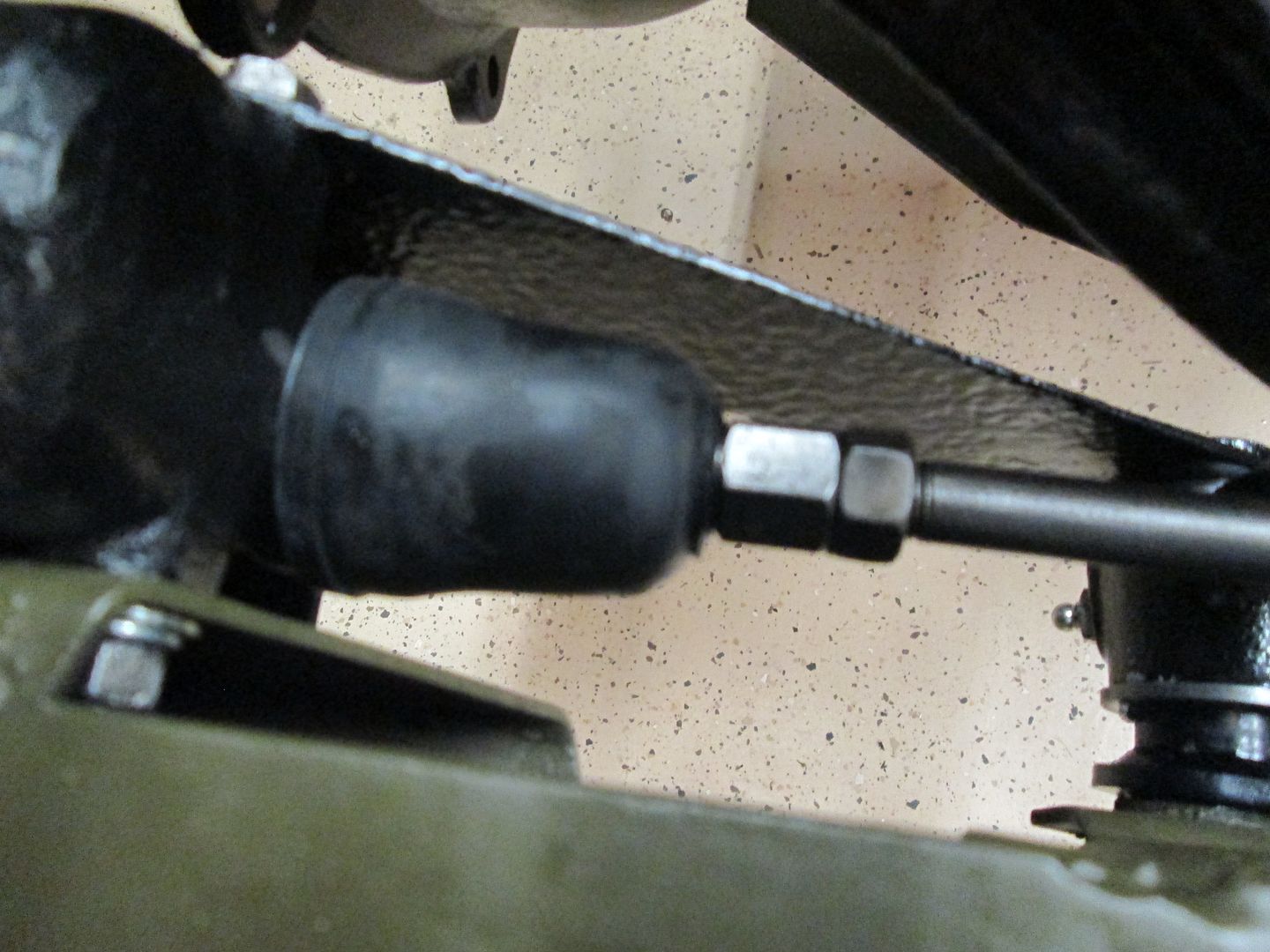 Slip the brake pedal onto the shaft, against the installed washer. There is a second washer, then the idler shaft brace, then a cotter pin, as pictured. 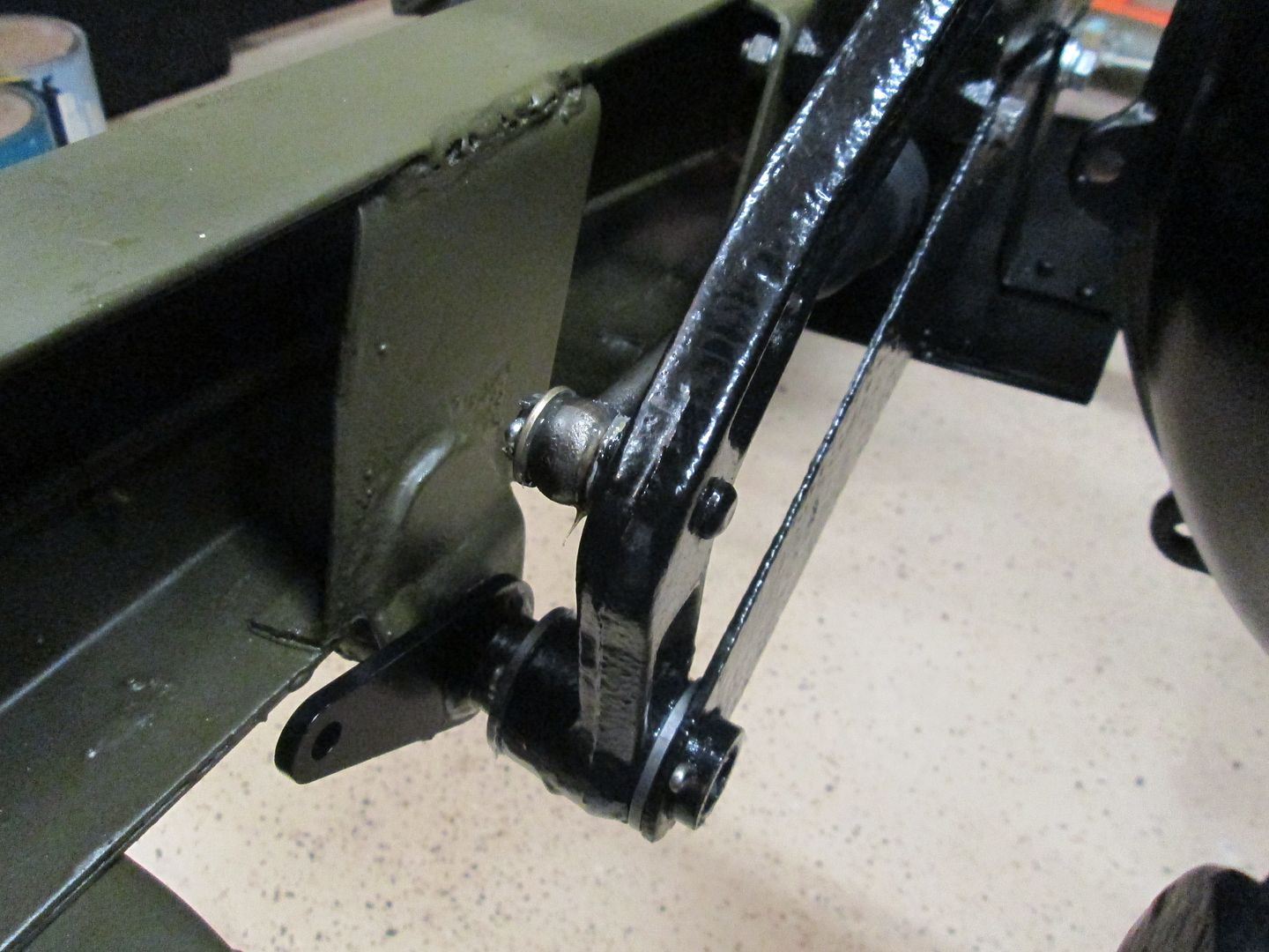 |
|
|
|
Post by athawk11 on Mar 14, 2014 10:32:08 GMT -5
I'm enjoying this thread. A very nicely done photo documentary! Hopefully you got the picture I sent. I put forth a challenge to all...
Take a single decent photo, showing a working brake pedal assembly, and showing all the components, on a fully assembled Willys Jeep. I contend that it can't be done!!!
Tim
|
|
Deleted
Deleted Member
Posts: 0
|
Post by Deleted on Mar 14, 2014 19:24:51 GMT -5
Tim, be careful, if the floor is rusted out and gone, and they put a tank in the back for the gas, you might just get a clear photo of it.  John |
|
Deleted
Deleted Member
Posts: 0
|
Post by Deleted on Mar 25, 2014 20:07:22 GMT -5
The NAPA p/n for the clevis, to make your own #16 release rod, is 732-1122 (brake yoke end), you will need 2, plus pins and cotter pins. Lee  |
|
|
|
Post by Haines Garage on Mar 26, 2014 9:27:04 GMT -5
Very valuable information, I am happy with the rod project.
I need to post my finished assembly pics....
|
|
|
|
Post by athawk11 on May 25, 2014 8:30:32 GMT -5
On one of my chassis runs with Whitey, I pressed on the clutch. All of the sudden…bammm! Pedal went to the floor. Whitey’s link is the primer red one in the photo. I was a mile away from my house when this happened. I walked home, grabbed the link off ODie, (Green one in the photo) and used it to get Whitey home. I made a new traditional link (unpainted one in the photo), but then decided to go the way of the Haines Garage. I made one for Whitey and ODie. I’ll keep the traditional links in my on board parts selection just in case another Willys Jeeper breaks theirs along a lonely mountain trail…  All painted up and ready for installation…  |
|
|
|
Post by Haines Garage on May 25, 2014 9:53:06 GMT -5
Sir Hawkridge ..
They look great!!
|
|